Stanley Meyer: Water Fuel Cell
Electronics World & Wireless World
( January 1991)
USP # 4,936,961 ~ Method for the Production
of a Fuel Gas
KeelyNet/Vangard Notes
USP # 4,826,581 ~ Controlled Process for the
Production of Thermal Energy from Gases...
USP # 4,798,661 ~ Gas Generator Voltage Control
Circuit
USP # 4,613,304 ~ Gas Electrical Hydrogen
Generator
USP # 4,465,455
~ Start-up/Shut-down
for a Hydrogen Gas Burner
USP # 4,421,474 ~ Hydrogen Gas Burner
USP # 4,389,981 ~ Hydrogen Gas Injector System
for Internal Combustion Engine
Dan Danforth: Molecular Dissociation of Water
Water Fuel Cell News Release (Winter/Spring
87/88)
Raum & Zeit 1(6) 63-68 (1990)
Patents Granted (@ 1990)
Water Fuel Cell R&D Format
Infinite Energy 19: 50-51 (1998) Obituary
Water-Powered
Car Video ( Link to http://www.lonelantern.org/collection.html
)
Excerpts from: Electronics World & Wireless World
( January 1991) ~ KeelyNet File MEYER1.ASC
Eye-witness accounts suggest that US inventor Stanley Meyer has developed
an electric cell which will split ordinary tap water into hydrogen and
oxygen with far less energy than that required by a normal electrolytic
cell.
In a demonstration made before Professor Michael Laughton, Dean of Engineering
at Mary College, London, Admiral Sir Anthony Griffin, a former controller
of the British Navy, and Dr Keith Hindley, a UK research chemist.
Meyer's cell, developed at the inventor's home in Grove City, Ohio, produced
far more hydrogen/oxygen mixture than could have been expected by simple
electrolysis.
Where normal water electrolysis requires the passage of current measured
in amps, Meyer's cell achieves the same effect in milliamps. Furthermore,
ordinary tap water requires the addition of an electrolyte such as sulphuric
acid to aid current conduction; Meyer's cell functions at greatest efficiency
with pure water.
According to the witnesses, the most startling aspect of the Meyer cell
was that it remained cold, even after hours of gas production.
Meyer's experiments, which he seems to be able to perform to order,
have earned him a series of US patents granted under Section 101. The granting
of a patent under this section is dependent on a successful demonstration
of the invention to a Patent Review Board.
Meyer's cell seems to have many of the attributes of an electrolytic
cell except that it functions at high voltage, low current rather than
the other way around. Construction is unremarkable. The electrodes ---
referred to as "excitors" by Meyer --- are made from parallel plates of
stainless steel formed in either flat or concentric topography. Gas production
seems to vary as the inverse of the distance between them; the patents
suggest a spacing of 1.5 mm produces satisfactory results.
The real differences occur in the power supply to the cell. Meyer uses
an external inductance which appears to resonate with the capacitance of
the cell --- pure water apparently possesses a dielectric constant of about
5 --- to produce a parallel resonant circuit. This is excited by a high
power pulse generator which, together with the cell capacitance and a rectifier
diode, forms a charge pump circuit. High frequency pulses build a rising
staircase DC potential across the electrodes of the cell until a point
is reached where the water breaks down and a momentary high current flows.
A current measuring circuit in the supply detects this breakdown and removes
the pulse drive for a few cycles allowing the water to "recover".
Research chemist Keith Hindley offers this description of a Meyer cell
demonstration: "After a day of presentations, the Griffin committee witnessed
a number of important demonstration of the WFC" (water fuel cell as named
by the inventor).
A witness team of independent UK scientifc observers testified that
US inventor Stanley Meyer successfully decomposed ordinary tap water into
constituent elements through a combination of high, pulsed voltage using
an average current measured only in milliamps. Reported gas evolution was
enough to sustain a hydrogen /oxygen flame which instantly melted steel.
In contrast with normal high current electrolysis, the witnesses report
the lack of any heating within the cell. Meyer declines to release details
which would allow scientists to duplicate and evaluate his "water fuel
cell". However, he has supplied enough detail to the US Patent Office to
persuade them that he can substantiate his 'power-from-water' claims.
One demonstration cell was fitted with two parallel plate "excitors".
Using tap water to fill the cell, the plates generated gas at very low
current levels --- no greater than a tenth of an amp on the ammeter, and
claimed to be milliamps by Meyer --- and this gas production increased
steadily as the plates were moved closer together and decreased as they
were separated. The DC voltage appeared to be pulsed at tens of thousands
of volts.
A second cell carried nine stainless steel double tube cell units and
generated much more gas. A sequence of photographs was taken showing gas
production at milliamp levels. When the voltage was turned up to its peak
value, the gas then poured off at a very impressive level.
"We did notice that the water at the top of the cell slowly became discolored
with a pale cream and dark brown precipitate, almost certainly the effects
of the chlorine in the heavily chlorinated tap water on the stainless steel
tubes used as "excitors".
He was demonstrating hydrogen gas production at milliamp and kilovolt
levels.
"The most remarkable observation is that the WFC and all its metal pipework
remained quite cold to the touch, even after more than twenty minutes of
operation. The splitting mechanism clearly evolves little heat in sharp
contrast to electrolysis where the electrolyte warms up quickly."
"The results appear to suggest efficient and controllable gas production
that responds rapidly to demand and yet is safe in operation. We clearly
saw how increasing and decreasing the voltage is used to control gas production.
We saw how gas generation ceased and then began again instantly as the
voltage driving circuit was switched off and then on again."
"After hours of discussion between ourselves, we concluded that Stan
Meyer did appear to have discovered an entirely new method for splitting
water which showed few of the characteristics of classical electrolysis.
Confirmation that his devices actually do work come from his collection
of granted US patents on various parts of the WFC system. Since they were
granted under Section 101 by the US Patent Office, the hardware involved
in the patents has been examined experimentally by US Patent Office experts
and their seconded experts and all the claims have been established."
"The basic WFC was subjected to three years of testing. This raises
the granted patents to the level of independent, critical, scientific and
engineering confirmation that the devices actually perform as claimed."
The practical demonstration of the Meyer cell appears substantially
more convincing than the para-scientific jargon which has been used to
explain it. The inventor himself talks about a distortion and polarization
of the water molecule resulting in the H:OH bonding tearing itself apart
under the electrostatic potential gradient, of a resonance within the molecule
which amplifies the effect.
Apart from the copious hydrogen/oxygen gas evolution and the minimal
temperature rise within the cell, witnesses also report that water within
the cell disappears rapidly, presumably into its component parts and as
an aerosol from the myriad of tiny bubbles breaking the surface of the
cell.
Meyer claims to have run a converted VW on hydrogen/oxygen mixture for
the last four years using a chain of six cylindrical cells. He also claims
that photon stimulation of the reactor space by optical fibre piped laser
light increases gas production.
The inventor is a protegee' of the Advanced Energy Institute.
USP # 4,936,961
Method for the Production of a Fuel Gas
Stanley Meyer
Related Application: This is a continuation-in-part of my co-pending
application Ser.; No. 081,859, filed 8/5/87, now U.S. Pat. No. 4,826, 581.
Field of Invention: This invention relates to a method of and apparatus
for obtaining the release of a fuel gas mixture including hydrogen and
oxygen from water.
BACKGROUND OF THE PRIOR ART
Numerous processes have been proposed for separating a water molecule
into its elemental hydrogen and oxygen components. Electrolysis is one
such process. Other processes are described in the United States patents
such as 4,344,831; 4,184,931; 4,023,545; 3,980, 053; and Patent Cooperation
Treaty application No. PCT/US80/1362, Published 30 April, 1981.
OBJECTS OF THE INVENTION
It is an object of the invention to provide a fuel cell and a process
in which molecules of water are broken down into hydrogen and oxygen gases,
and other formerly dissolved within the water is produced. As used herein
the term "fuel cell" refers to a single unit of the invention comprising
a water capacitor cell, as hereinafter explained, that produces the fuel
gas in accordance with the method of the invention.
Brief Description of the Drawings
FIG. 1 illustrates a circuit useful in the process.
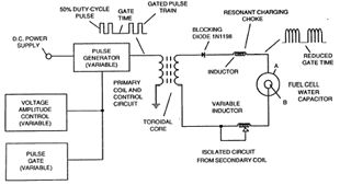
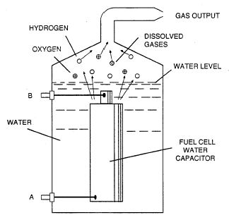
FIG. 2 shows a perspective of a "water capacitor" element used in the
fuel cell circuit.
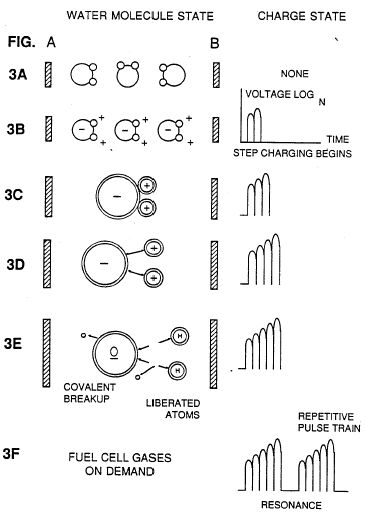
FIGS. 3A through 3F are illustrations depicting the theoretical bases
for the phenomena encountered during operation of the invention herein.
Description of the Preferred Embodiment:
In brief, the invention is a method of obtaining the release of a gas
mixture including hydrogen on oxygen and other dissolved gases formerly
entrapped in water, from water consisting of:
(A) providing a capacitor, in which the water is included as a dielectric
liquid between capacitor plates, in a resonant charging choke circuit that
includes an inductance in series with the capacitor;
(B) subjecting the capacitor to a pulsating, unipolar electric voltage
field in which the polarity does not pass beyond an arbitrary ground, whereby
the water molecules within the capacitor are subjected to a charge of the
same polarity and the water molecules are distended by their subjection
to
electrical polar forces;
(C) further subjecting in said capacitor to said pulsating electric
field to achieve a pulse frequency such that the pulsating electric field
induces a resonance within the water molecule;
(D) continuing the application of the pulsating frequency to the capacitor
cell after resonance occurs so that the energy level within the molecule
is increased in cascading incremental steps in proportion to the number
of pulses;
(E) maintaining the charge of said capacitor during the application
of the pulsing field, whereby the co-valent electrical bonding of the hydrogen
and oxygen atoms within said molecules is destabilized such that the force
of the electrical field applied, as the force is effective within the molecule,
exceeds the bonding force of the molecule, and hydrogen and oxygen atoms
are liberated from the molecule as elemental gases; and
(F) collecting said hydrogen and oxygen gases, and any other gases that
were formerly dissolved within the water, and discharging the collected
gases as a fuel gas mixture.
The process follows the sequence of steps shown in the following Table
1 in which water molecules are subjected to increasing electrical forces.
In an ambient state, randomly oriented water molecules are aligned with
respect to a molecule polar orientation.
They are next, themselves polarized and "elongated" by the application
of an electrical potential to the extent that covalent bonding of the water
molecule is so weakened that the atoms dissociate and the molecule breaks
down into hydrogen and oxygen elemental components.
Engineering design parameters based on known theoretical principles
of electrical circuits determine the incremental levels of electrical and
wave energy input required to produce resonance in the system whereby the
fuel gas comprised of a mixture of hydrogen, oxygen, and other gases such
as air were formerly dissolved within the water, is produced.
TABLE 1
Process Steps:
The sequence of the relative state of the water molecule and/or hydrogen/oxygen/other
atoms:
A. (ambient state) random
B. Alignment of polar fields
C. Polarization of molecule
D. Molecular elongation
E. Atom liberation by breakdown of covalent bond
F. Release of gases
In the process, the point of optimum gas release is reached at a circuit
resonance. Water in the fuel cell is subjected to a pulsating, polar electric
field produced by the electrical circuit whereby the water molecules are
distended by reason of their subjection to electrical polar forces of the
capacitor plates.
The polar pulsating frequency applied is such that the pulsating electric
field induces a resonance in the molecule. A cascade effect occurs and
the overall energy level of specific water molecules is increased in cascading,
incremental steps.
The hydrogen and oxygen atomic gases, and other gas components formerly
entrapped as dissolved gases in water, are released when
the resonant energy exceeds the covalent bonding force of the water
molecule. A preferred construction material for the capacitor plates
is stainless steel T-304 which is non-chemical reactive with
water, hydrogen, or oxygen.
An electrically conductive material which is inert in the fluid environment
is a desirable material of construction for the electrical field plates
of the "water capacitor" employed in the circuit.
Once triggered, the gas output is controllable by the attenuation of
operational parameters. Thus, once the frequency of resonance is identified,
by varying the applied pulse voltage to the water fuel cell assembly, gas
output is varied.
By varying the pulse shape and/or amplitude or pulse train sequence
of the initial pulsing wave source, final gas output is varied. Attenuation
of the voltage field frequency in the form of OFF and ON pulses likewise
affects output.
The overall apparatus thus includes an electrical circuit in which a
water capacitor having a known dielectric property is an element. The fuel
gases are obtained from the water by the disassociation of the water molecule.
The water molecules are split into component atomic elements (hydrogen
and oxygen gases) by a voltage stimulation process called the electrical
polarization process which also releases dissolved gases entrapped in the
water.
From the outline of physical phenomena associated with the process described
in Table 1, the theoretical basis of the invention considers the respective
states of molecules and gases and ions derived from liquid water.
Before voltage stimulation, water molecules are randomly dispersed throughout
water in a container.
When a unipolar voltage pulse train such as shown in FIGS. 3B through
3F is applied to positive and negative capacitor plates, an increasing
voltage potential is induced in the molecules in a linear, step like charging
effect.
The electrical field of the particles within a volume of water including
the electrical field plates increases from a low energy state to a high
energy state successively is a step manner following each pulse-train as
illustrated figuratively in the depictions of FIG. 3A through 3F.
The increasing voltage potential is always positive in direct relationship
to negative ground potential during each pulse. The voltage polarity on
the plates which create the voltage fields remains constant although the
voltage charge increases. Positive and negative voltage "zones" are thus
formed simultaneously in the electrical field of the capacitor plates.
In the first stage of the process described in Table 1, because the
water molecule naturally exhibits opposite electrical fields in a relatively
polar configuration (the two hydrogen atoms are positively electrically
charged relative to the negative electrically charged oxygen atom), the
voltage pulse causes initially randomly oriented water molecules in the
liquid state to spin and orient themselves with reference to positive
and negative poles of the voltage fields applied.
The positive electrically charged hydrogen atoms of said water molecule
are attracted to a negative voltage field; while, at the same time, the
negative electrically charged oxygen atoms of the same water molecule are
attracted to a positive voltage field.
Even a slight potential difference applied to inert, conductive plates
of a containment chamber which forms a capacitor will initiate polar atomic
orientation within the water molecule based on polarity differences.
When the potential difference applied causes the orientated water molecules
to align themselves between the conductive plates, pulsing causes the voltage
field intensity to be increased in accordance with FIG. 3B. As further
molecule alignment occurs, molecular movement is hindered.
Because the positively charged hydrogen atoms of said aligned molecules
are attracted in a direction opposite to the negatively charged oxygen
atoms, a polar charge alignment or distribution occurs within the molecules
between said voltage zones, as shown in FIG. 3B. And as the energy level
of the atoms subjected to resonant pulsing increases, the stationary water
molecules become elongated as shown in FIGS. 3C and 3D. Electrically charged
nuclei and electrons are attracted toward opposite electrically charged
equilibrium of the water molecule.
As the water molecule is further exposed to an increasing potential
difference resulting from the step charging of the capacitor, the electrical
force of attraction of the atoms within the molecule to the capacitor plates
of the chamber also increase in strength. As a result, the covalent bonding
between which form the molecule is weakened --- and ultimately terminated.
The negatively charged electron is attracted toward the positively charged
hydrogen atoms, while at the same time, the negatively charged oxygen atoms
repel electrons.
In a more specific explanation of the "sub-atomic" action the occurs
in the water fuel cell, it is known that natural water is a liquid which
has a dielectric constant of 78.54 at 20 degrees C. and 1 atm pressure.
[Handbook of Chemistry & Physics, 68th ed., CRC Press(Boca Raton, Florida
(1987-88)), Section E-50. H20(water)].
When a volume of water is isolated and electrically conductive plates,
that are chemically inert in water and are separated by a distance, are
immersed in water, a capacitor is formed, having a capacitance determined
by the surface area of the plates, the distance of their separation and
the dielectric constant of water.
When water molecules are exposed to voltage at a restricted current,
water takes on an electrical charge. By the laws of electrical attraction,
molecules align according to positive and negative polarity fields of the
molecule and the alignment field. The plates of the capacitor constitute
such as alignment field when a voltage is applied.
When a charge is applied to a capacitor, the electrical charge of the
capacitor equals the applied voltage charge; in a water capacitor, the
dielectric property of water resists the flow of amps in the circuit, and
the water molecule itself, because it has polarity fields formed by the
relationship of hydrogen and oxygen in the covalent bond, and intrinsic
dielectric property, becomes part of the electrical circuit, analogous
to a "microcapacitor" within the capacitor defined by the plates.
In the Example of a fuel cell circuit of FIG. 1, a water capacitor is
included. The step-up coil is formed on a conventional toroidal core formed
of a compressed ferromagnetic powered material that will not itself become
permanently magnetized, such as the trademarked "Ferramic 06# "Permag"
powder as described in Siemens Ferrites Catalog, CG-2000-002-121, (Cleveland,
Ohio) No. F626-1205". The core is 1.50 inch in diameter and 0.25 inch in
thickness. A primary coil of 200 turns of 24 gauge copper wire is provided
and coil of 600 turns of 36 gauge wire comprises the secondary winding.
In the circuit of FIG 1, the diode is a 1N1198 diode which acts as a
blocking diode and an electric switch that allows voltage flow in one direction
only. Thus, the capacitor is never subjected to a pulse of reverse polarity.
The primary coil of the toroid is subject to a 50% duty cycle pulse.
The toroidal pulsing coil provides a voltage step-up from the pulse generator
in excess of five times, although the relative amount of step-up is determined
by preselected criteria for a particular application. As the stepped-up
pulse enters first inductor (formed from 100 turns of 24 gauge wire 1 inch
in diameter), an electromagnetic field is formed around the inductor, voltage
is switched off when the pulse ends, and the field collapses and produces
another pulse of the same polarity i.e., another positive pulse is formed
where the 50% duty cycle was terminated. Thus, a double pulse frequency
is produced; however, in pulse train of unipolar pulses, there is a brief
time when pulses are not present.
By being so subjected to electrical pulses in the circuit of FIG. 1,
water confined in the volume that includes the capacitor plates takes on
an electrical charge that is increased by a step charging phenomenon occurring
in the water capacitor. Voltage continually increases (to about 1000 volts
and more) and the water molecules starts to elongate.
The pulse train is then switched off; the voltage across the water capacitor
drops to the amount of the charge that the water molecules have taken on,
i.e., voltage is maintained across the charged capacitor. The pulse train
is the reapplied.
Because a voltage potential applied to a capacitor can perform work,
the higher the voltage the higher the voltage potential, the more work
is performed by a given capacitor. In an optimum capacitor that is wholly
non-conductive, zero (0) current flow will occur across the capacitor.
Thus, in view of an idealized capacitor circuit, the object of
the water capacitor circuit is to prevent electron flow through the circuit,
i.e. such as occurs by electron flow or leakage through a resistive element
that produces heat.
Electrical leakage in the water will occur, however, because of some
residual conductivity and impurities or ions that may be otherwise present
in the water. Thus, the water capacitor is preferably chemically inert.
An electrolyte is not added to the water.
In the isolated water bath, the water molecule takes on charge, and
the charge increases. The object of the process is to switch off the covalent
bonding of the water molecule and interrupt the subatomic force, i.e. the
electrical force or electromagnetic force, that binds the hydrogen and
oxygen atoms to form a molecule so that the hydrogen and oxygen separate.
Because an electron will only occupy a certain electron shell (shells
are well known) the voltage applied to the capacitor affects the electrical
forces inherent in the covalent bond. As a result of the charge applied
by the plates, the applied force becomes greater than the force of the
covalent bonds between the atom of the water molecule; and the water molecule
becomes elongated. When this happens, the time share ratio of the
electron shells is modified.
In the process, electrons are extracted from the water bath; electrons
are not consumed nor are electrons introduced into the water bath by the
circuit as electrons are conventionally introduced in as electrolysis process.
There may nevertheless occur a leakage current through the water.
Those hydrogen atoms missing electrons become neutralized; atoms are
liberated from the water. The charged atoms and electrons are attracted
to the opposite polarity voltage zones created between the capacitor plates.
The electrons formerly shared by atoms in the water covalent bond are reallocated
such that neutral elemental gases are liberated.
In the process, the electrical resonance may be reached at all levels
of voltage potential. The overall circuit is characterized as a "resonant
charging choke" circuit which is an inductor in series with a capacitor
that produces a resonant circuit. [SAMS Modern Dictionary of Electronics,
Rudolf Garff, copyright 1984, Howard W. Sams & Co. (Indianapolis, Ind.),
page 859.]
Such a resonant charging choke is on each side of the capacitor. In
the circuit, the diode acts as a switch that allows the magnetic field
produced in the inductor to collapse, thereby doubling the pulse frequency
and preventing the capacitor from discharging. In this manner a continuous
voltage is produced across the capacitor plates in the water bath; and
the capacitor does not discharge. The water molecules are thus subjected
to a continuously charged field until the breakdown of the covalent
bond occurs.
As noted initially, the capacitance depends on the dielectric properties
of the water and the size and separation of the conductive elements forming
the water capacitor.
EXAMPLE 1
In an example of the circuit of FIG. 1 (in which other circuit element
specifications are provided above), two concentric cylinders 4 inches long
formed the water capacitor of the fuel cell in the volume of water. The
outside cylinder was 0.75 inch in outside diameter; the inner cylinder
was 0.5 inch in outside diameter.
Spacing from the outside of the inner cylinder to the inner surface
of the outside cylinder was 0.0625 inch. Resonance in the circuit was achieved
at a 26 volt applied pulse to the primary coil of the toroid at 0 KHz,
and the water molecules disassociated into elemental hydrogen and
oxygen and the gas released from the fuel cell comprised a mixture of hydrogen,
oxygen from the water molecule, and gases formerly dissolved in the water
such as the atmospheric gases or oxygen, nitrogen, and argon.
In achieving resonance in any circuit, as the pulse frequency is adjusted,
the flow of amps is minimized and the voltage is maximized to a peak. Calculation
of the resonance frequency of an overall circuit is determined by known
means; different cavities have a different frequency of resonance
dependant on parameters of the water dielectric, plate size, configuration
and distance, circuit inductors, and the like. Control of the production
of fuel gas is determined by variation of the period of time between
a train of pulses, pulse amplitude and capacitor plate size and configuration,
with corresponding value adjustments to other circuit components.
The wiper arm on the second conductor tunes the circuit and accommodates
to contaminants in water so that the charge is always applied to the capacitor.
The voltage applied determines the rate of breakdown of the molecule into
its atomic components. As water in the cell is consumed, it is replaced
by any appropriate means or control system.
Variations of the process and apparatus may be evident to those skilled
in the art.
What is claimed is:
1. A method of obtaining the release of a gas mixture including
hydrogen and oxygen and other dissolved gases formerly entrapped
in water, from water, consisting of: (A) providing a capacitor in which
water is included as a dielectric between capacitor plates, in a resonant
charging choke circuit that includes an inductance in
series with the capacitor;
(B) subjecting the capacitor to a pulsating, unipolar electric charging
voltage in which the polarity does not pass beyond an arbitrary ground,
whereby the water molecules within the capacitor plates;
(C) further subjecting the water in said capacitor to a pulsating electric
field resulting from the subjection of the capacitor to the charging voltage
such that the pulsating electric field induces a resonance within the water
molecules;
(D) continuing the application of the pulsating charging voltage to
the capacitor after the resonance occurs so that the energy level within
the molecules is increased in cascading incremental steps in proportion
to the number of pulses;
(E) maintaining the charge of said capacitor during the application
of the pulsating charge voltage, whereby the covalent electrical bonding
of the hydrogen and oxygen atoms within said molecules is destabilized,
such that the force of the electrical field applied to the molecules exceeds
the bonding force within the molecules, and the
hydrogen and oxygen atoms are liberated from the molecules as elemental
gases.
2. The method of claim 1 including the further steps of collecting
said liberated gases and any other gases that were formerly dissolved within
the water and discharging said collected gases as a fuel gas mixture.
Keelynet/Vangard Notes
1N1198 Diode is also a NTE 5995 or a ECG 5994. It is a 40A 600
PIV Diode (the 40A is over kill and may not be needed).
Stainless Steel "T304" is a type of weldable Stainless, but other types
should work the same. "T304" is just the more common type of Stainless
tubing available.
The outer tube figures out to be 3/4" 16 gauge (.060 "wall") tube (a
common size) cut to 4 inch length.
The inner tube figures out to be 1/2" 18 gauge (.049 "wall", this is
a common size for this tube, but the actual gauge cannot be figured from
this patent documentation, but this size should work) cut to 4 inch length.
You should also attach the two leads to the Stainless, using Stainless
solid rod (1/6 dia would do) and USE LEAD FREE SOLDER ! (you may
want the purified water that is returned to drink some day).
You also need to figure out a way to keep the two tubes separated from
each other. This could be done with small pieces of plastic. They cannot
block the flow of water into/out of the tubes.
It was not indicated if the inner tube is full of water or not. The
guess here is that it is full of water, and this doesn't effect the device
at all.
The Patent doesn't say but I would think that insulating the leads with
some type of tubing up to the tubes would be electrically correct (and
probably wouldn't hurt).
The pulse frequency was not printed, it is estimated from the size
of the coils and transformer that the frequency doesn't exceed 50 Mhz.
Don't depend on this being fact, it's just a educated guess.
The circuit to do this is not shown, just empty boxes. It's time to
get out your SCOPE and try things! Don't forget to share your results with
others ! GREED is why this type of thing never gets out into the world
to do some GOOD. If you want to make some money, make something PRACTICAL
that WORKS and that PEOPLE can use in their every day lives, then sell
it! Holding onto information like this only hurts ALL OF US !!
USP # 4,826,581
Controlled Process for the Production of Thermal Energy
from Gases and Apparatus Useful Therefore
Stanley Meyer
(May 2, 1989)
Abstract ~
A method of and apparatus for obtaining the release of energy from
a gas mixture including hydrogen and oxygen in which charged ions are stimulated
to an activated state, and then passed through a resonant cavity, where
successively increasing energy levels are achieved, and finally passed
to an outlet orifice to produce thermal explosive energy.
Inventors: Meyer; Stanley A. (3792 Broadway, Grove City, OH 43123)
Appl. No.: 081859 ~ Filed: August 5, 1987
Current U.S. Class: 204/157.41; 204/164 ~ Intern'l Class: C07G
013/00
Field of Search: 204/164,157.41,157.44
References Cited:U.S. Patent Documents ~
4,233,109 Nov., 1980 Nishizawa 204/164.
4,406,765 Sep., 1983 Higashi, et al. 204/164.
4,687,753 Aug., 1987 Fiato et al. 204/157.
4,695,357 Sep., 1987 Boussert 204/157.
Primary Examiner: Kalafut; Stephen J. ~
Attorney, Agent or Firm: Porter, Wright, Morris & Arthur
Claims ~
1. A method of obtaining the release of energy from a gas mixture including
hydrogen and oxygen consisting of: (A) providing a first gas mixture including
at least a portion of hydrogen and oxygen gases; (B) subjecting the gas
mixture to a pulsating, polar electric field whereby electrons of the gas
atoms are distended in their orbital fields by reason of their subjection
to electrical polar forces, at a frequency such that the pulsating electric
field induces a resonance with respect to an electron of the gas atom;
(C) cascading said gas atoms with respect to the pulsating electric field
such that the energy level of the resonant electron is increased in cascading
incremental steps; (D) ionizing said gas atoms; (E) subjecting the ionized
gas atoms to electromagnetic wave energy having a predetermined frequency
to induce a further election resonance in the ion, whereby the energy level
of the electron is successively increased; (F) extracting further electrons
from the resonating ions while such ions are in an increased energy state
to destabilize the nuclear and electron configuration of said ions; and
(G) subjecting the destabilized ions to thermal ignition.
2. An apparatus for obtaining the release of energy from a gas mixture
including hydrogen and oxygen consisting of successively interconnected:
(A) first means for providing a first gas mixture including at least a
portion of hydrogen and oxygen gas; (B) second means for providing a pulsating,
polar electric field to the gas mixture, whereby electrons of the gas atoms
are distended in their orbital fields by reason of their subjection to
electrical polar forces, at a frequency such that the pulsating electric
field induces a resonance with respect to an electron of the gas atom;
and the energy level of the resonant electron is increased in cascading,
incremental steps; (C) third means for providing a further electric field
to ionize said gas atoms; (D) an electromagnetic wave energy source for
subjecting the ionized gas atoms to wave energy of a predetermined frequency
to induce a further election resonance in the ion, whereby the energy level
of the electron is further successively increased; (E) an electron sink
for extracting electrons from the resonating ions while such ions are in
an increased energy state to destabilize the nuclear and electron configuration
of said ions; (F) fourth means for directing particle flow in a continuous
manner through the electric fields, wave energy source and electron sink
to a final orifice at which the destabilized ions are thermally ignited;
and (G) a final orifice at which the mixture initially provided by the
first means, after having passed through and been processed by the preceeding
means of the apparatus, is thermally ignited.
Description~
FIELD OF THE INVENTION
This invention relates to a method of and apparatus for obtaining the
release of energy from a gas mixture including hydrogen and oxygen in which
charged ions are stimulated to an actived state, and then passed through
a resonant cavity, where successively increasing energy levels are achieved,
and finally passed to an outlet orifice to produce thermal explosive energy.
BACKGROUND OF THE PRIOR ART
Processes have been proposed for many years in which controlled energy
producing reactions of atomic particles are expected to occur under "cold"
conditions. [See. e.q.. Rafelski, J. and Jones, S.E., "Cold Nuclear Fusion,"
Scientific American, July, 1987, page 84]. The process and apparatus described
herein are considered variations to and improvements in processes by which
energy is derived from excited atomic components in a controllable manner.
OBJECTS OF THE INVENTION
It is an object of the invention to realize significant energy-yield
from water atoms. Molecules of water are broken down into hydrogen and
oxygen gases. Electrically charged gas ions of opposite electrical polarity
are activated By Express Mail No. 26224690 on August 5, 1987 by electromagnetic
wave energy and exposed to a high temperature thermal zone. Significant
amounts of thermal energy with explosive force beyond the gas burning stage
are released.
An explosive thermal energy under a controlled state is produced. The
process and apparatus provide a heat energy source useful for power generation,
aircraft, rocket engines, or space stations.
BRIEF DESCRIPTION OF THE DRAWINGS
FIG. 1 illustrates a staged arrangement of apparatus useful in the process,
beginning with a water inlet and culminating in the production of thermal
explosive energy.
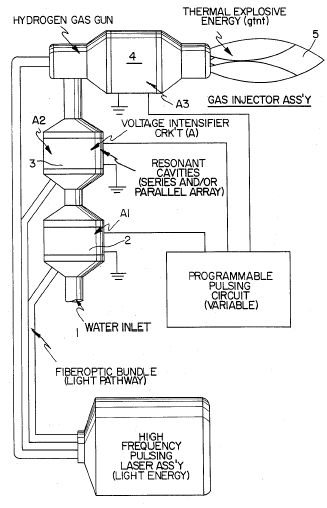
FIG. 2A shows a cross-section of a circular gas resonant cavity used
in the final stage assembly of FIG. 1.
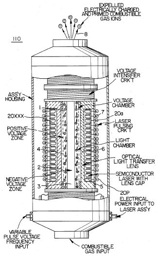
FIG. 2B shows an alternative final stage injection system useful in
the apparatus of FIG. 1.
[Error in patent: Figure not shown]
FIG. 2C shows an optical thermal lens assembly for use either final
stage of FIG. 2A or FIG. 2B.
[Error in patent: Figure not shown]
FIGS. 3A, 3B, 3C and 3D are illustrations depicting various theoretical
bases for atomic phenomena expected to occur during operation of the invention
herein.
[Error in patent: Figure not shown]
FIG. 4 is an electrical schematic of the voltage source for the gas
resonant cavity.
[Error in patent: Figure not shown]
FIGS. 5A and 5B, respectively, show (A) an electron extractor grid used
in the injector assemblies of FIG. 2A and FIG. 2B, and (B) the electronic
control circuit for the extractor grid.
[Error in patent: Figure not shown]
[Actual Figures: ]
Figure 3
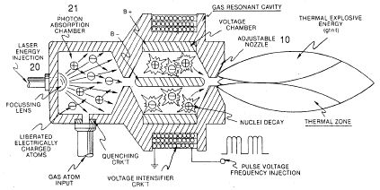 .
.
Figure 4
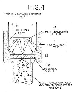
Figure 5
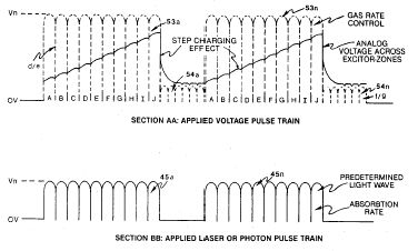
Figure 6
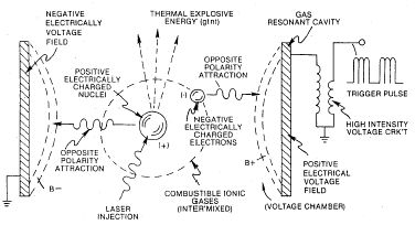
Figure 7
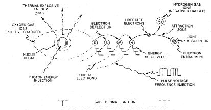
Figure 8
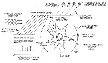
Figure 9
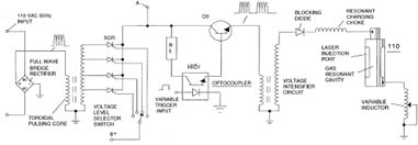
Figure 10
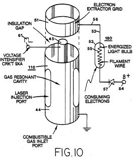
Figure 11
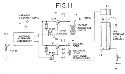
DESCRIPTION OF THE PREFERRED EMBODIMENT
The hydrogen fracturing process, follows the sequence of steps shown
in the following Table I in which beginning with water molecules, the molecule
is subjected to successively increasing electrical, wave energy and thermal
forces. In the succession of forces, radomly oriented water molecules are
aligned with respect to molecular polar orientation and are themselves
polarized and "elongated" by the application of an electric potential to
the extent that covalent bonding of the water molecule is so weakened that
the atoms disassociate and the molecule breaks down into hydrogen and oxygen
elemental components. The released atomic gases are next ionized and electrically
charged in a vessel while being subjected to a further energy source that
promotes inter-particle impact in the gas at an increased overall energy
level. Finally, the atomic particles in the excited gas, having achieved
successively higher energy levels, are subjected to a laser or electromagnetic
wave energy source that produces atomic destabilization and the final release
of thermal explosive energy. Engineering design parameters based on known
theoretical principles of atomic physics determine the incremental levels
of electrical and wave energy input required to produce resonance in each
stage of the system. Instead of a dampening effect, a resonant energization
of the molecule, atom or ion provides a compounding energy interaction
resulting in the final energy release.
TABLE I
______________________________________
PROCESS STEPS LEADING TO IGNITION
______________________________________
RELATIVE STATE OF WATER MOLECULE AND/OR
HYDROGEN/OXYGEN/OTHER ATOMS
RANDOM
1st Stage
ALIGNMENT
Water to Gas
POLARIZATION
2nd Stage
MOLECULAR ELONGATION Gas
Ionization
ATOM LIBERATION
3rd Stage
LIQUID TO GAS IONIZATION Priming
ELECTRICAL CHARGING EFFECT
Final Stage
PARTICLE IMPACT
Ignition
ELECTROMAGNETIC WAVE, LASER OR
PHOTON INJECTION
ELECTRON EXTRACTION
ATOMIC DESTABILIZATION
THERMAL IGNITION
______________________________________
After the first stage in which water is broken down into its atomic
components in a mixture of hydrogen, oxygen and formerly dissolved entrapped
gasses, the gas atoms become elongated during electron removal as the atoms
are ionized. Laser, or light wave energy of a predetermined frequency is
injected into a containment vessel in a gas ionization process. The light
energy absorbed by voltage stimulated gas nuclei causes destabilization
of gas ions still further. The absorbed laser energy causes the gas nuclei
to increase in energy state, which, in turn, causes electron deflection
to a higher orbital shell.
The electrically charged and laser primed combustible gas ions from
a gas resonant cavity may be directed into an optical thermal lens assembly
for triggering. Before entry into the optimal thermal lens, however, electrons
are stripped from the ions and the atom is destabilized. The destabilized
gas ions which are electrically and mass unbalanced atoms having highly
energized nuclei are pressurized during spark ignition. The unbalanced,
destablized atomic components thermally interact; the energized and unstable
hydrogen gas nuclei collide with highly energized and unstable oxygen gas
nuclei, causing and producing thermal explosive energy beyond the gas burning
stage. The ambient air gas components in the initial mixture aid the thermal
explosive process under a controlled state.
In the process, the point of optimum energy-yield is reached when the
electron deficient oxygen atoms (having less than a normal number of electrons)
lock onto and capture a hydrogen atom electron prior to or during thermal
combustion of the hydrogen/oxygen mixture. Atomic decay results in the
release of energy.
In a general outline of the method, a first gas mixture including at
least a portion of hydrogen and oxygen gases is provided. The gas mixture
is subjected to a pulsating, polar electric field whereby electrons of
the gas atoms are distended in their orbital fields by reason of their
subjection to electrical polar forces. The polar pulsating frequency applied
is such that the pulsating electric field induces a resonance with respect
to an election of the gas atom. A cascade effect results and the energy
level of specific resonating electron is increased in cascading, incremental
steps.
Next, the gas atoms are ionized and subjected to electro-magnetic wave
energy having a predetermined frequency to induce a further election resonance
in the ion, whereby the energy level of the election is successively increased.
Electrons are extracted from the resonating ions while such ions are in
an increased energy state to destabilize the nuclear electron configuration
of said ions; and the gas mixture of destabilized ions is thermally ignited.
In the apparatus shown in FIG. 1, water is introduced at inlet 1 into
a first stage water fracturing module 2 in which water molecules are broken
down into hydrogen, oxygen and released entrapped gas components by an
electrical disassociation process and apparatus such as shown in my co-pending
application Ser. No. 835,564, filed March 3, 1986, which is incorporated
herein by reference. The released atomic gases and other gas components
formerly entrapped as dissolved gases in water may be introduced to a successive
stage 3 or other number of like resonant cavities, which are arranged in
either a series or parallel combined array. The successive energization
of the gas atoms provides a cascading effect, successively increasing the
voltage stimulation level of the released gasses as they sequentially pass
through cavities 2, 3, etc. In a final stage, an injector system 4, of
a configuration of the type shown in FIGS. 2A or 2B, receives energized
atomic and gas particles where the particles are subjected to further energy
input, electrical excitation and thermal stimulation, whereby thermal explosive
energy results 5, which may be directed thru a lens assembly of the type
shown in FIG. 2C to provide a controlled thermal energy output.
Electromagnetic wave activated and electrically charged gas ions of
hydrogen and oxygen (of opposite polarity) are expelled from the cascaded
cells 2, 3, etc. The effect of cascading successively increases the voltage
stimulation level of the released gases, which then are directed to the
final injector assembly 4. In the injector assembly, gas ions are stimulated
to a yet higher energy level. The gases are continually exposed to a pulsating
laser or other electromagnetic wave energy source together with a high
intensity oscillating voltage field that occurs within the cell between
electrodes or conductive plates of opposite electrical polarity. A preferred
construction material for the plates is a stainless steel T-304 which is
non-chemically reactive with water, hydrogen, or oxygen. An electrically
conductive material which is inert in the fluid environment is a desirable
material of construction for the electrical field producing plates, through
which field the gas stream of activated particles passes. Gas ions of opposite
electrical charges reach and maintain a critical energy level state. The
gas ions are oppositely electrically charged and subjected to oscillating
voltage fields of opposite polarity and are also subjected to a pulsating
electromagnetic wave energy source. Immediately after reaching critical
energy, the excited gas ions are exposed to a high temperature thermal
zone in the injection cell, 4, that causes the excited gas ions to undergo
gas combustion. The gas ignition triggers atomic decay and releases thermal
energy, 5, with explosive force.
Once triggered, the thermal explosive energy output is controllable
by the attenuation of operational parameters. With reference to FIG. 4A,
for example, once the frequency of resonance is identified, by varying
applied pulse voltage to the initial water fuel cell assemblies, 2, 3,
the ultimate explosive energy output is likewise varied. By varying the
pulse shape and/or amplitude or pulse train sequence of the electromagnetic
wave energy source, final output is varied. Attenuation of the voltage
field frequency in the form of OFF and ON pulses likewise affects output
of the staged apparatus. Each control mechanism can be used separately,
grouped in sections, or systematically arranged in a sequential manner.
The overall apparatus thus includes means for providing a first gas
mixture consisting of at least a portion of hydrogen and oxygen gas. The
gases may be obtained by disassociation of the water molecule. An electrical
circuit of the type shown in FIG. 4 provides a pulsating, polar electric
field to the gas mixture as illustrated in FIG. 3A, whereby electrons of
the gas atoms are distended in their orbital fields by reason of their
subjection to electrical polar forces, changing from the state conceptually
illustrated by FIG. 3B to that of FIG. 3C, at a frequency such that the
pulsating electric field induces a resonance with respect to electrons
of the gas atoms. The energy level of the resonant electrons is thereby
increased in cascading, incremental steps. A further electric field to
ionize said gas atoms is applied and an electromagnetic wave energy source
for subjecting the ionized gas atoms to wave energy of a predetermined
frequency to induce a further electron resonance in the ion, whereby the
energy level of the election is successively increased is an additional
element of the apparatus as shown in FIG. 3D.
An electron sink, which may be in the form of the grid element shown
in FIG. 5A, extracts further electrons from the resonating ions while such
ions are in an increased energy state and destabilizes the nuclear electron
configuration of the ions. The "extraction" of electrons by the sink means
is coordinated with the pulsating electrical field of the resonant cavity
produced by the circuit of FIG. 4, by means of an interconnected synchronization
circuit, such as shown in FIG. 5B. A nozzle, 10 in FIG. 2B, or thermal
lens assembly, FIG. 2C, provides the directing means in which the destabilized
ions are finally thermally ignited.
As previously noted, to reach and trigger the ultimate atomic decay
of the fuel cell gases at the final stage, sequential steps are taken.
First, water molecules are split into component atomic elements (hydrogen
and oxygen gases) by a voltage stimulation process called the electrical
polarization process which also releases dissolved gases entrapped in the
water (See my co-pending application for letters patent, Ser. No. 835,
564, supra). In the injector assembly, a laser produced light wave or other
form of coherent electromagnetic wave energy capable of stimulating a resonance
within the atomic components is absorbed by the mixture of gases (hydrogen/oxygen/ambient
air gases) released by the polarization process. At this point, as shown
in FIG. 3B, the individual atoms are subjected to an electric field to
begin an ionization process.
The laser or electromagnetic wave energy is absorbed and causes gas
atoms to lose electrons and form positively charged gas ions. The energized
hydrogen atoms which, as ionized, are positively charged, now accept electrons
liberated from the heavier gases and attract other negatively charged gas
ions as conceptually illustrated in FIG. 3C. Positively and negatively
charged gas ions are re-exposed to further pulsating energy sources to
maintain random distribution of ionized atomic gas particles.
The gas ions within the wave energy chamber are subjected to an oscillating
high intensity voltage field in a chamber 11 in FIGS. 2A and 2B formed
within electrodes 12 and 13 in FIGS. 2A and 2B of opposite electrical polarity
to produce a resonant cavity. The gas ions reach a critical energy state
at a resonant state.
At this point, within the chamber, additional electrons are attracted
to said positive electrode; whereas, positively charged ions or atomic
nuclei are attracted to the negative electrode. The positive and negative
attraction forces are co-ordinate and operate on said gas ions simultaneously;
the attraction forces are non-reversible. The gas ions experience atomic
component deflection approaching the point of electron separation. At this
point electrons are extracted from the chamber by a grid system such as
shown in FIG. 5A. The extracted electrons are consumed and prevented from
re-entering the chamber by a circut such as shown in FIG. 5B. The elongated
gas ions are subjected to a thermal heat zone to cause gas ignition, releasing
thermal energy with explosive force. During ionic gas combustion, highly
energized and stimulated atoms and atom nuclei collide and explode during
thermal excitation. The hydrogen fracturing process occurring sustains
and maintains a thermal zone, at a temperature in excess of normal hydrogen/oxygen
combustion temperature, to wit, in excess of 2500.degree. F. To cause and
maintain atomic elongation depicted in FIG. 3C before gas ignition, a voltage
intensifier circuit such as shown in FIG. 4 is utilized as a current restricting
voltage source to provide the excitation voltage applied to the resonant
cavity. At the same time the interconnected eletron extractor circuit,
FIG. 5B, prevents the reintroduction of electrons back into the system.
Depending on calculated design parameters, a predetermined voltage and
frequency range may be designed for any particular application or physical
configuration of the apparatus.
In the operation of the assembly, the pulse train source for the gas
resonant cavity shown at 2 and 3 in FIG. 1 may be derived from a circuit
such as shown in FIG. 4. It is necessary in the final electron extraction
that the frequency with which electrons are removed from the system by
sequenced and synchronized with the pulsing of the gas resonant cavity
In the circuit of FIG. 5B, the coordination or synchronization of the circuit
with the circuit of FIG. 4 may be achieved by interconnecting point "A"
of the gate circuit of FIG. 5B to coordinate point "A" of the pulsing circuit
of FIG. 4.
Together the hydrogen injector assembly 4 and the resonant cavity assemblies
2, 3 form a gas injector fuel cell which is compact, light in weight and
design variable. For example, the hydrogen injector system is suited for
automobiles and jet engines. Industrial applications require larger systems.
For rocket engine applications, the hydrogen gas injector system is positioned
at the top of each resonant cavity arranged in a parallel cluster array.
If resonant cavities are sequentially combined in a parallel/series array,
the hydrogen injection assembly is positioned after the exits of said resonant
cavities are combined.
From the outline of physical phenomena associated with the process described
in Table 1, the theoretical basis of the invention considers the respective
states of molecules, gases and ions derived from liquid water. Before voltage
stimulation, water molecules are randomly dispersed throughout water within
a container. When a unipolar voltage pulse train such as shown in FIG.
3A (53a xxx 53n) is applied, an increasing voltage potential is induced
in the molecules, gases and/or ions in a linear, step-like charging effect.
The electrical field of the particles within a chamber including the electrical
field plates increases from a low energy state (A) to a high energy state
(J) in a step manner following each pulse-train as illustrated in FIG.
3A. The increasing voltage potential is always positive in direct relationship
to negative ground potential during each pulse. The voltage polarity on
the plates which create the voltage fields remains constant. Positive and
negative voltage "zones" are thus formed simultaneously.
In the first stage of the process described in Table 1, because the
water molecule naturally exhibits opposite electrical fields in a relatively
polar configuration (the two hydrogen atoms are positively electrically
charged relative to the negative electrically charged oxgen atom), the
voltage pulse causes initially randomly oriented water molecules in the
liquid state to spin and orient themselves with reference to positive and
negative poles of the voltage fields applied. The positive electrically
charged hydrogen atoms of said water molecule are attracted to a negative
voltage field; while, at the same time, the negative electrically charged
oxygen atoms of the same water molecule an attracted to a positive voltage
field. Even a slight potential difference applied to the inert, conductive
plates of a containment chamber will initiate polar atomic orientation
within the water molecule based on polarity differences.
When the potential difference applied causes the orientated water molecules
to align themselves between the conductive plates, pulsing causes the voltage
field intensity to be increased in accordance with FIG. 3A. As further
molecular alignment occurs, molecular movement is hindered. Because the
positively charged hydrogen atoms of said aligned molecules are attracted
in a direction opposite to the negatively charged oxygen atoms, a polar
charge alignment or distribution occurs within the molecules between said
voltage zones, as shown in FIG. 3B. And as the energy level of the atoms
subjected to resonant pulsing increases, the stationary water molecules
become elongated as shown in FIG. 3C. Electrically charged nuclei and electrons
are attracted toward opposite electrically charged voltage zones--disrupting
the mass equilibium of the water molecule.
In the first stage, as the water molecule is further exposed to a potential
difference, the electrical force of attraction of the atoms within the
molecule to the electrodes of the chamber also increases in intensity.
As a result, the covalent bonding between said atoms which forms the molecule
is weakened and ultimately terminated. The negatively charged electron
is attracted toward the positively charged hydrogen atoms, while at the
same time, the negatively charged oxygen atoms repel electrons.
Once the applied resonant energy caused by pulsation of the electrical
field in the cavities reaches a threshold level, the disassociated water
molecules, now in the form of liberated hydrogen, oxygen, and ambient air
gases begin to ionize and lose or gain electrons during the final stage
in the injector assembly. Atom destablization occurs and the electrical
and mass equilibrium of the atoms is disrupted. Again, the positive field
produced within the chamber or cavity that encompasses the gas stream attracts
negatively charged ions while the positively charged ions (and/or hydrogen
nuclei) are attracted to the negative field. Atom stabilization does not
occur because the pulsating voltage applied is repetitive without polarity
change. A potential of approximately several thousand volts triggers the
ionization state.
As the ionized particles accumulate within said chamber, the electrical
charging effect is again an incremental stepping effect that produces an
accumlative increased potential while, at the same time, resonance occurs.
The components of the atom begin to "vibrate" at a resonant frequency such
that an atomic instability is created. As shown in FIG. 3D, a high energy
level is achieved, which then collapses resulting in the release of thermal
explosive energy. Particle impact occurs when liberated ions in a gas are
subjected to further voltage. A longitudinal cross section of a gas resonant
cavity is shown in FIG. 2A. To promote gas ionization, electromagnetic
wave energy such as a laser or photon energy source of a predetermined
wave length and pulse-intensity is directed to and absorbed by the ions
forming said gas. In the device of FIG. 2A, semiconductor optical lasers
20a-20p, 20xxx surround the gas flow path. In the device of FIG. 2B, photon
energy 20 is injected into a separate absorption chamber 21. The incremental
stimulation of nuclei to a more highly energized state by electromagnetic
wave energy causes electron deflection to a higher orbital state. The Pulse
rate as well as intensity of the electromagnetic wave source is varied
to match the absorption rate of ionized particles to produce the stepped
incremental increase in energy. A single laser coupled by means of fiber
optic light guides is an alternative to the plurality of lasers shown in
FIG. 2B. Continued exposure of the gas ions to different forms of wave
energy during voltage stimulation maintains individual atoms in a destabilized
state and prevents atomic stabilization.
The highly energized gas ions are thermally ignited when said combustible
gas ions pass from injector 4 and enter into and pass through a nozzle,
10 in FIG. 2B, or an optical thermal lens assembly such as shown in FIG.
2C. In FIG. 2C, the combustible gas ions are expelled through and beyond
a quenching circuit, 30, and reflected by lenses, 31 and 32, back and forth
through a thermal heat zone, 33, prior to atomic breakdown beyond exiting
through a final port, 34. A quenching circuit is a restricted orifice through
which the particle stream passes such that flashback does not occur. (See
my application Ser. No. 835, 564, supra.) The deflection shield or lens,
31, superheats beyond 3,000.degree. F. and the combustible gas ions passing
through said exiting-ports are regulated to allow a gas pressure to form
inside said thermal zone. The energy yield is controlled by varying the
applied voltage, or Pulse-train since said thermal-lens assembly is self-adjusting
to the flow-rate of said ionized and primed gases. The combustible ionic
gas mixture is composed of hydrogen, oxygen, and ambient air gases. The
hydrogen gas provides the thermal explosive force, the oxygen atoms aid
the gas thermal ignition, and the ambient air gases retard the gas thermal
ignition process to a controllable state. As the combustible gas mixture
is exposed to a voltage pulse train, the stepped increasing voltage potential
causes said moving gas atoms to become ionized (losing or gaining electrons)
and changes the electrical and mass equilibrium of said atoms. Gases that
do not undergo the gas ionization process may accept the liberated electrons
(electron entrapment) when exposed to light or photon stimulation. The
electron extractor grid circuit, FIGS. 5A and 5B, is applied to the assembly
of FIG. 2A or FIG. 2B, and restricts electron replacement. The extractor
grid, 56, is applied adjacent to electric field producing members, 44 and
45, within the resonant cavity. The gas ions incrementally reach a critical-state
which occurs after a high energy resonant state. At this point the atoms
no longer tolerate the missing electrons, the unbalanced electrical field,
and the energy stored in the nucleus. Immediate collapse of the system
occurs and energy is released as the atoms decay into thermal explosive
energy.
The repetitive application of a voltage pulse train (A through J of
FIG. 3A) incrementally achieves the critical state of said gas ions. As
the gas atoms or ions (la xxx ln) shown in FIG. 3C become elongated during
electron removal, electromagnetic wave energy of a predetermined frequency
and intensity is injected. The wave energy absorbed by the stimulated gas
nuclei and electrons causes further destabilization of the ionic gas. The
absorbed energy from all sources causes the gas nuclei to increase in energy
state, and induces the ejection of electrons from the nuclei.
To further stimulate the electron entrapment process beyond the atomic
level (capturing the liberated electrons during the hydrogen fracturing
process) the electron extractor grid (as shown in FIG. 5A) is placed in
spaced relationship to the gas resonant cavity structure shown in FIG.
2A. The electron extractor grid is attached to an electrical circuit (such
as shown in FIG. 5B) that allows electrons to flow to an electrical load,
55, when a positive electrical potential is placed on the opposite side
of said electrical load. The electrical load may be a typical power consuming
device such as a light bulb or resistive heat producing device. As the
positive electrical potential is switched on or pulse-applied, the negative
charged electrons liberated in the gas resonant cavity are drawn away and
enter into resistive load where they are consumed and released as heat
or light energy. The consuming electrical circuit can be directly connected
to the gas resonant cavity positive electrical voltage zone. The incoming
positive wave form applied to resonant cavity voltage zone through a blocking
diode is synchronized with the pulse train applied to the gas resonant
cavity by the circuit of FIG. 4 via alternate gate circuit. As one pulse
train is gated "ON," the other pulse train is switched "OFF." A blocking
diode directs the electron flow to said electrical load while resistive
wire prevents voltage leakage during pulse train "ON" time.
The electron extraction process is maintained during gas flow-rate change
by varying the trigger pulse rate in relationship to applied voltage. The
electron extraction process also prevents spark-ignition of the combustible
gases traveling through the gas resonant cavity because electron build-up
and potential sparking is prevented.
In an optical thermal lens assembly or thrust-nozzle, such as shown
in FIG. 2C, destablized gas ions (electrically and mass unbalanced gas
atoms having highly energized nuclei) can be pressurized during spark-ignition.
During thermal interaction, the highly energized and unstable hydrogen
gas nuclei collide with the highly energized and unstable oxygen gas nuclei
and produce thermal explosive energy beyond the gas burning stage. Other
ambient air gases and ions not otherwise consumed limit the thermal explosive
process.
Variations of the process and apparatus may be evident to those skilled
in the art.
USP 4,798,661
Gas Generator Voltage Control Circuit
Stanley Meyer
Abstract ~
A power supply in a system utilizing as a source of fuel a generator
for separating hydrogen and oxygen gasses from natural water and having
the capabilities to control the production of gasses by varying the amplitude
of the voltage and/or the pulse repetition rate of the voltage pulses applied
to a pair of plate exciters in a vessel of natural water, comprising a
sequence of circuitry operative to limit the current of a d.c. potential
to a minimum value relative to the magnitude of the voltage applied to
the plate exciters. The circuits each function up to a given magnitude
of voltage to inhibit and curtail the flow of electrons from the plate
exciter having the negative voltage potential applied thereto. The first
circuit operative from a first magnitude of voltage comprises converting
the voltage potential applied to the plate exciters to a unipolar pulse
voltage d.c. of a repetitive frequency. The next circuit varies the duty
cycle of the unipolar pulse voltage d.c.; followed by rearranging the application
of the voltage to the exciters to individual exciters each having the voltage
applied thereto independently of the other plate exciters in the generator.
The next circuit comprises an electron inhibitor that prevents the flow
of electrons; the circuit being in the terminal line between the negative
plate exciter and ground. In those applications of the generator wherein
excessively high voltage is to be applied to the plate exciters for a very
high yield of gasses, a second electron inhibitor of a unique structure
is serially connected with the first electron inhibiter. The second named
inhibiter having a relatively fixed value and the first inhibiter connected
in series is variable to fine tune the circuits to eliminate current flow.
Claims
I claim:
In a generator for producing a mixture of hydrogen and oxygen and other
dissolved gas from natural water which generator includes at least a pair
of plate exciters within a water containing vessel, a variable voltage
source for applying a pulsating predetermined potential difference between
the plates and wherein the rate of production of the mixture of gasses
is controlled by varying at least one of the amplitude of the voltage and
the pulse repetition rate of the pulsating potential difference applied
to the plate exciters.
The variable voltage source includes a means for restricting the current
flow between the plate exciters to a minimum value relative to a predetermined
potential difference applied to the plates, the improvement in the means
for restricting said current flow comprising: variable voltage source means
for converting an input voltage potential to unipolar d.c. voltage pulses
that are applied to the exciter plates and have a pulsating potential difference
when measured from an arbitrary ground.
There is also a means for regulating the voltage pulses in a repetitive
frequency to inhibit the current flow caused by electron leakage between
the plate exciters resulting from the amplitude of the applied voltage
potential whereby said current flow is inhibited from exceeding a first
minimum level.
The input voltage is an alternating current voltage and said circuit
for converting said alternating current voltage to unipolar d.c. voltage
pulses further comprises, means for varying the frequency of said alternating
current voltage input to further inhibit electron leakage upon increasing
the amplitude of the voltage applied to the plate exciters to a second
level.
The variable voltage source is an alternating current voltage for converting
alternating current voltage to unipolar d.c. voltage pulses also comprises
a transformer having primary and secondary windings, and a rectifier circuit
connected across said secondary windings.
The transformer further includes variable inductive means for varying
the output frequency of the voltage induced in said secondary winding to
further inhibit electron leakage upon increasing the amplitude of the voltage
applied to the plate exciters to a third level.
The variable voltage source also has a pulse forming circuit for varying
the duty cycle of the unipolar d.c. voltage pulses to a predetermined repetition
rate to inhibit electron leakage upon increasing the amplitude of the voltage
applied to the plate exciters to a fourth level.
A means is further provided to vary the amplitude of the duty cycle
pulses to vary the rate of production of the hydrogen and oxygen gasses,
further comprising means for correlating the repetition of said duty cycle
pulses with the amplitude of said duty cycle pulses to provide an average
amplitude pulse below the amplitude level causing electron leakage.
The variable voltage source of the generator of claim 5 wherein said
varying of the duty cycle of said unipolar d.c. voltage pulses to inhibit
electron leakage is a periodic varying and aperiodic varying.
It also has circuit means for varying the amplitude of said duty cycle
pulses from a first gradient level to a second gradient level, and a means
for varying the duty cycle pulses to a plurality of distinctive gradient
levels.
It also has circuit means for nonuniformly varying the duty cycle pulses
to a plurality of distinctive gradient levels.
The unipolar d.c. voltage pulses in the duty cycle is non-repetitive.
Varying of the duty cycle of said pulses to inhibit electron leakage
comprise circuit means for varying the amplitude from a first gradient
minimum level to a plurality of gradient levels. Gradient levels of amplitude
represent demand functions for a utilitarian device.
The circuit further comprises means for varying the frequency
of the alternating voltage including a transformer having a primary winding
and a secondary winding, and wherein said means is connected to the input
of the primary of said transformer.
A pair of plate exciters are spatially positioned in natural water with
a physical distance there between of a wavelength to that of a particular
frequency of the voltage back and forth motion between said exciter plates,
and means for varying said unipolar d.c. voltage pulses in frequency to
match the wavelength distance of the pair of plate exciters.
The pair of plate exciters are spatially positioned in the water with
a physical distance there between of a wavelength to that of a particular
frequency of the voltage back and forth motion between said exciter plates,
and pulse forming means for varying the duty cycle of said unipolar d.c.
voltage; and a means for varying said duty cycle pulse in repetition rate
to match the wavelength distance of said pair of plate exciters.
The pair of plate exciters are spatially positioned in water with
a physical distance therebetween of a wavelength to that of particular
frequncey of the voltage back and forth motion between the exciter plates,
and pulse forming means for varying the duty cycle of said unipolar d.c.
voltage ; and a means for varying the duty cycle pulse in repetition rate
to match the wavelength distance of the pair of plate exciters, and means
for varying the amplitude of said duty cycle pulses to a minimum level
to maintain resonance between said pair of plate exciters; and a means
for varying the repetition frequency of said unipolar d.c. voltage pulses
to vary the rate of generation of gasses.
The negative plate has a ground and an electron inhibiting resistive
element connected between the negative plate and ground, providing a means
to vary the resistive element with a variable resistor to maximize electron
inhibition.
The variable voltage source of the generator of claim 28 wherein the
amplitude of the voltage induced in the secondary is dependant on the number
of turns in said secondary winding.
There is a circuit component means for converting an input voltage to
unipolar d.c. voltage pulses of a repetitive frequency to inhibit electron
leakage upon varying the amplitude of the applied voltage above a first
predetermined amplitude level, a pulse forming circuit for varying the
duty cycle of said unipolar d.c. voltage pulses to a predetermined repetition
rate to inhibit electron leakage upon varying the amplitude of the voltage
beyond a second level of amplitude circuit means for varying the frequency
of said unipolar d.c. voltage pulses to inhibit electron leakage upon varying
the amplitude of the applied voltage above a third predetermined level,
a ground and a variable resistive element connected between the plate exciter
having a negative voltage applied it and ground to limit electron leakage
upon varying the amplitude of the voltage beyond a fourth level of amplitude,
a pair of plates and a resistive material sandwiched therebetween connected
to said plate exciter having said negative voltage connected thereto and
the end of the variable resistor opposite to the ground connection, to
limit electron leakage upon varying the amplitude of said voltage applied
to said plates bea fifth level.
Description ~
BACKGROUND AND CROSS REFERENCES
The phenomena of physics was discovered that the hydrogen atoms in the
water molecule will take on a positive charge whereas the oyxgen atom in
the water molecule takes on a negative charge when the water molecule is
exposed to an electrical voltage. The two hydrogen positive charged atoms
and the one oxygen negative charged atoms, in magnitude, are in a state
of equilibrium .
In my co-pending patent application, Ser. No. 302,807, now abandoned
for Hydrogen Generator, the above noted principle of polarization is utilized.
The simultaneous application of a positive voltage pulse to one plate exciter
and a negative polarized voltage pulse to the other plate exciter in a
vessel of natural water, will form polarized voltage electrical zones around
the plates of a respective polarity. The positive voltage plate exciter
zone attracts the negative charged atoms of the water molecule and the
negative voltage plate exciter zone attracts the positive charged hydrogen
atoms of the water molecule.
The opposing attractive forces causes the hydrogen and oxygen atoms
to disassociate from the water molecule; and thereby, release the hydrogen
and oxygen gasses. In that natural water is utilized in the generator and
that natural water contains a considerable percentage of ambient air, ambient
air gas will also be released similarly to the oxygen and hydrogen gasses
from the water molecule.
The above described process is apparently not a chemical reaction process
such as in Faraday's Laws. In that process electrolyte is added to distilled
water to draw current. The reaction of the electrolyte with that of the
corrosive electrodes releases the hydrogen and oxygen gasses.
Characteristically, Faraday's Laws requires:
"The rate of deomposition of an electrolyte is dependant on current
and independant of voltage. xxx will depend on current regardless of voltage,
provided the voltage exceeds a minimum for a potential."
In the voltage dependant/current restricted process of my co-pending
patent application, the disassociation of the hydrogen and oxygen atoms
from the water molecule, is attributed to the physical force attraction
of the polarized zones adjacent the plate exciters on the charged hydrogen
and oxygen atoms having a polarity opposite to that of the polarized zone.
This physical force is exemplified in my co-pending patent application,
Ser. No. 422,594, filed Sept. 24, 1982, now abandoned for Hydrogen Generator
Resonant Cavity, wherein the principle of physics that physical motion
of an element between spatially positioned structures will resonate ifthe
distance between the structures, in wavelengths, is matched to the frequency
of the force causing the physical motion, is utilized in a practical and
useful embodiment.
The d.c. voltage with current restricted, applied to the pair of plate
exciters spatially positioned in a vessel of natural water, is pulsed.
The pulsing voltage on the plate exciters applying a physical force is
matched in repetition rate to the wavelength of the spacing of the plate
exciters. The physical motion of the hydrogen and oxygen charged atoms
being attracted to the opposite polarity zones will go into resonance.
The self sustaining resonant motion of the hydrogen and oxygen atoms of
the water molecule greatly enhances their disassociation from the water
molecule.
In my co-pending patent application, Ser. No. 411,977, filed Aug. 25,
1982, for Controlled Hydrogen Gas Flame, the gasses separated from the
water, the hydrogen and oxygen together with the ambient air non-combustible
gasses, are mixed as they are released by the generator. The mixture of
gasses are collected in a pressure chamber in the generator and thereafter
expelled through a nozzle having a port configuration with openings dependant
on the mixture of gasses. The nozzle is connected directly to the collection
chamber and ignited.
The gas mixture has a reduced velocity and temperature of the burning
flame from that which would occur solely with a hydrogen and oxygen mixture.
To further control the flame, there is added to the mixture other non-combustible
gasses in a controlled amount. Accordingly, the nozzle ports are related
to the temperature and velocity of the flame. The several ports will accommodate
flames of greater size without the danger of flashback or blowout such
as would happen with a single flame.
This physical force is further demonstrated in the plate separation
phenomena of the first aforementioned co-pending patent application. Simply,
the closer the spacing between the plate exciters the greater the attractive
force of the opposite polarity plate exciters on the charged hydrogen and
oxygen atoms of the water molecule. With a given spacing, an increase in
the magnitude of the voltage applied to the plate exciters will result
in an increase in the rate of production of the gasses. With a voltage
of a fixed amplitude a variation in the plate exciter spacing will affect
the rate of production of the gasses. An increase in the spacing will result
in less generation, whereas a decrease in the spacing of the plate exciters
will result in an increase in gasses.
THEORETICAL ANALYSIS
The electrical phenomena of a positive potential voltage applied to
one plate exciter and the application of a negative voltage potential applied
to another plate exciter positioned in a vessel of water, may now be considered.
Distilled water, like air, having no conductive meduim, will inherently
inhibit electron leakage. The magnitude of the applied voltage to the pair
of plate exciters is correlated with the physical force on the electron
movement. The magnitude of the initial force and the magnitude of the force
to leak the electrons, and thereafter cause current flow, may be calculated
or more readily empirically determined.
A small amplitude negative voltage applied to the negative plate exciter,
will cause a physical disturbance to the movement of the floating electrons.
However, the small amplitude voltage is insufficient to cause the electrons
to leak and enter the attractive field force area of the positive plate.
As the magnitude of the applied voltage is increased, the disturbance to
the movement of the electrons is increased. With a further increase in
the amplitude of the voltage applied to the plate exciters -- to a limiting
level, the resistance of the meduim to the attractive force of the opposite
polarity exciter plate on the electron leakage will be overcome.
As the electron leakage enhances, the flow of the electrons to the positive
plate exciter gradually increases as they enter the attractive field of
the positive plate. Upon attaining a heavy flow of electrons reaching the
positive plate attractive area, arcing will occur. An electrical arc is
formed between the two plate exciters. When this occurs a direct short
conductive flow of current will flow across the plates.
The electrical arc between the pair of plate exciters will form a direct
line of conductivity; current will flow unrestricted. Upon the electron
leakage attaining a direct short, the current is at a maximum. The voltage
being subjected to the current takeover decreases gradually upon initial
electron leakage and thereafter drops as the flow of electrons increases.
When the electron leakage arcs over to the positive potential plate exciter,
the voltage will drop to zero.
As stated above, the spacing between the pair of plate exciters in a
vessel of water having a d.c. voltage applied, is correlated with the gas
production rate. The closer the spacing between the pair of plate exciters,
the greater the yield of gas generated. If the spacing of the pair of plate
exciters is altered to a minimum spacing level, the attractive force of
the positive polarity plate will overcome the resistance of the water meduim.
Electron leakage will occur and from gradually to rapidly increase until
arcing between the pair of plate exciters forms a direct path and consequently
a direct short.
The distance between the plates and the amplitude of the voltage applied,
each independantly affect the other. The two variable factors are interrelated;
the one being variable relative to the other. The spacing being inversely
proportional to the amplitude of the voltage.
SUMMARY OF THE INVENTION
In the utilization of a generator for the separation of the hydrogen
and oxygen gasses from water; and the production of the gasses is varied
by varying the amplitude of the voltage and/or the pulse rate--duty cycle
of the pulsed d.c. voltage applied to the plate exciters in a vessel of
water.
The present invention comprises a power supply with the applied voltage
to the pair of plate exciters variable from zero upward to extremely high
voltages; but yet, that inhibits the electron leakage.
The power supply of the present invention includes circuitry for an
increased production of the generation of the gasses through varying the
amplitude of the voltage applied to the plate exciters. The circuitry includes
means and components for restriction of the electron leakage (current flow).
The applied voltage to the pair of plate exciters is a unipolar pulse
d.c. voltage of a repetitive frequency. Alternate power circuitry is utilized.
In the first embodiment the input voltage is alternating current fed to
a bridge rectifier; whereas in the second preferred embodiment, the input
voltage is direct current applied to the primary of a rotating field secondary
winding.
With a very low level of amplitude of the voltage applied to the plate
exciters, no electron leakage from the negative potential plate exciter
to the positive potential attractive field will occur. An amplitude of
the voltage above a first forceful level will cause electron leakage. The
circuitry of the invention overcomes the electron leakage with the application
to the plate exciters the aforesaid pulsed d.c. voltage.
An increase in amplitude of the applied voltage above a second level,
will result in electron leakage.
To obtain additional gas production without electron leakage, circuitry
in the power supply prevents electron leakage by varying the duty cycle
of the pulsed d.c.voltage applied to the plate exciters. The varying levels
of amplitude of the duty cycle pulses effectively restrains the electrons
from the B+ attractive field.
The pulsating d.c. voltage and the duty cycle pulses have a maximum
amplitude of the level that would cause electron leakage. Varying of the
amplitude to an amplitude of maximum level to an amplitude below the maximum
level of the pulses, provide an average amplitude below the maximum limit;
but with the force of the maximum limit.
In most instances of a practical application of the hydrogen and oxygen
generator the pair of plate exciters will be several pairs connected in
parallel. There will be one terminal to the positive voltage and another
terminal to the negative voltage. A further expediency to eliminate electron
leakage is attained by eliminating the large surface area probability of
stray electrons.
It is noted that the first two circuit components and the multiple connections
for restricing electron leakage relates to the plate exciter having the
negative voltage applied thereto. That is the circuitry overcomes the attractive
force of the B+ potential field. Additional circuitry is provided for very
high yield gas production above the aforesaid upper limits, in the negative
applied voltage plate exciter.
A circuit is included in the negative plate exciter that practicaly
eliminates electron flow; that is, the electrons are prevented from reaching
the negative plate exciter and thereby eliminating the affect of the attractive
force of the B+ field. A current limiting resister connected between the
negative plate exciter and ground, prevents current flow--electron leakage
to the the opposite polarity field.
The circuit comprises a limiter resistor connected between the negative
plate and ground that blocks current flow--electron leakage to the negative
plate. The practical elimination of the current has no affect on the voltage,
in the preferred embodiment, since there is no voltage drop.
In a sophisticated embodiment, the limiting resistor comprises a unique
structure of poorly conductive material having a resistive mixture sandwiched
therebetween. A second resistor of the variable type is serially connected
to the unique limiter for tuning. The value of the limiting resistance
is determined by the current passing therethrough. The variable is employed
until the ammeter reads zero or close to zero as possible.
The sandwich type limiter is varied in value by controlling the mixture
of resistive material to binder.
The circuitry and expedients to inhibit the electron leakage at all
levels of the magnitude of the voltage applied to the plate exciters is
a sequence of steps and functions operable from predetermined circuit components.
The order of the circuit functions is set and preferably not altered; however,
each of the specific variables can be varied independantly and varied with
interrelated function to the other.
The phenomena that the spacing between two objects is related to the
wavelength of a physical motion between the two objects is utilized herein.
A relatively small increase in amplitude will yield an output several magnitudes
greater when the motion of the water molecule is moving to and fro with
a repetition rate to match the resonant length of the spacing between the
pair of exciters.
OBJECTS OF THE INVENTION
It is a principle object of the present invention to provide:
a power supply for a hydrogen and oxygen gas generator wherein varying
the voltage amplitude varies the rate of generation of the gasses generated.
such a power supply that includes circuitry to permit voltage to be
varied in amplitude with current restrict to a minimum relative to the
amplitude of the voltage.
such a power supply for a hydrogen and oxygen generator wherein the
electron leakage between the plate exciters is inhibited.
a power supply for a hydrogen and oxygen generator including circuitry
for a unipolar pulse d.c. voltage of a repetitive frequency from either
an alternating or a direct current input.
a power supply having varying levels of voltage indicative of varing
levels of gas generation that is programmable with a utilitarian device,
particularly, when the generator has exciters spaced a distance in wavelength
matched by the voltage pulse frequency.
BRIEF DESCRIPTION OF DRAWINGS
FIG. 1 is an overall illustration of the present invention in a preferred
embodiment; the components shown partly in block schematic and partly pictorially.
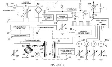
FIG. 2 is a first waveform illustrating the unipolar pulse d.c voltage
of repetitive frequency with a uniform duty cycle.
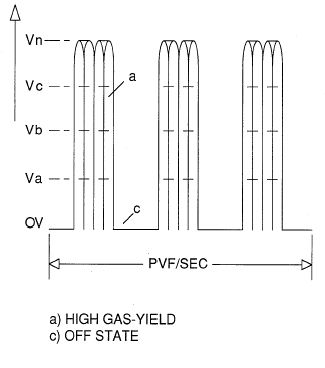 FIG. 3 illustrates the unipolar pulse voltage with a continuous repetitive
frequency.
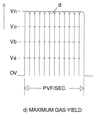 FIG. 4 illustrates the unipolar pulse voltage of a repetitive frequency
having a uniform duty cycle from a low gradient level to high gradient
level; FIG. 4A illustrates the duty cycle as being non-uniform and between
gradient levels; FIG. B illustrates the duty cycle comprising varying gradient
levels and of non-uniform repetition; and FIG. 4C illustrates the varying
gradient levels as being uniform.
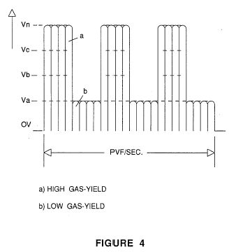
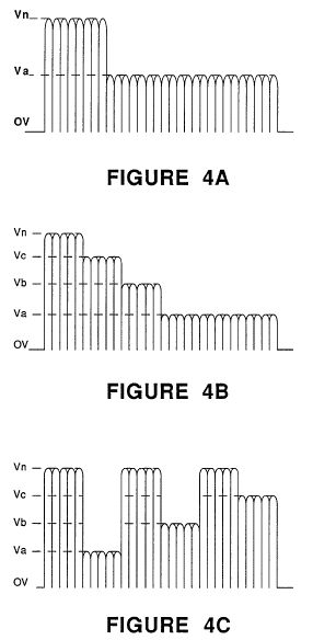
FIG. 5 illustrates partly schematic and partly in block the pulse frequency
generator from a direct current voltage source.
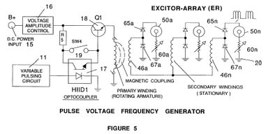 FIG. 6 is a schematic of the circuitry for programming the varying levels
of voltage to practical applications.
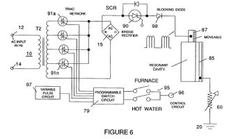 FIG. 7 is a crossectional perspective of a multiple layer sandwich resistive
element for inhibiting electron leakage.
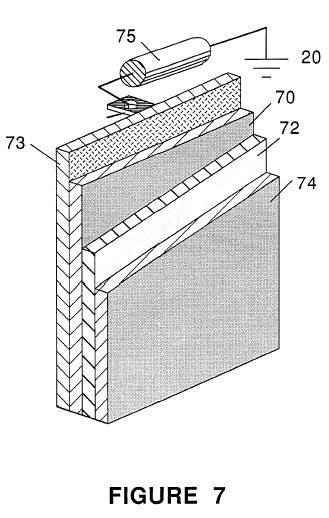 FIG. 8 is a graphical illustration of the varying limitations of voltage
amplitude for inhibiting electron leakage.
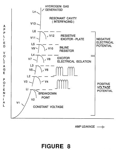 DETAILED DESCRIPTION
Referring to the drawings and in particular to FIG. 1, there is illustrated
the present invention in its preferred embodiment of a power supply for
the aforementioned hydrogen and oxygen gas generator, providing variable
amplitude voltage with inhibited electron leakage.
The alternating current rectifier circuit 10 comprises input alternating
current terminals 12 and 14. Switch 13 is a typical on/off switch. Transformer
10 is an inductive primary and secondary transformer connected to a bridge
rectifier 15. The inductive field 11 of the transformer 10 is variable
in a known manner to yield a variable frequency alternating voltage/current
to the primary winding. The bridge 15 arms are connected across the input
of the secondary winding of the transformer 10. The upper and lower arms
are connected across the extreme ends of the secondary winding and the
left hand arm is connected to the output of the rectifier 15. The right
arm is connected to ground 20. The rectifier inverts the negative swing
of the alternatng current and thereby results in an output voltage pulse
of a frequency twice that of the input frequency of the alternating current
voltage applied to the terminals 12 and 14.
It is appreciated that if the alternating current voltage is varied
in frequency by the variable inductive field 11, the output frequency across
the bridge 15 will still be twice the frequency of the alternating voltage
across the secondary of the transformer secondary winding 10.
The power supply of FIG. 1 includes a variable circuit 30 for varying
the amplitude of the rectified voltage by rectifier 15. The variable voltage
circuit , in turn, is directly controlled by the gas rate function separately,
sequential, and together with the phenomena of a reseonant cavity.
The waveform output of the bridge is shown as a unipolar d.c. voltage
pulse of a repetitive frequency. It is noted that the pulse voltage is
not filtered and the plate effect is utilized.
As stated, a voltage with an amplitude below the minimum level for example,
with a given size apparatus, 2.5 volts (L-1 of FIG. 8) when applied to
the pair of plate exciters, is insufficient amplitude to force the electrons
to leak from the negative plate exciter.
The hydrogen and oxygen gasses will be separated from the water at the
low level of voltage amplitude; and the gasses generated will also be at
the minimum.
Above the minimum level (L-1 of FIG. 8) of amplitude, the applied voltage
will have a sufficient force to agitate and cause movement of the electrons
around the negative plate exciter. As a consequence electron leakage would
take place.
To overcome the forceful effect on the electrons around the negative
plate exciter, but apply a voltage of increased amplitude for an increase
in gas production, the first step in a sequence is utilized. The pulsed
d.c. voltage having a frequency predetermined by the input alternating
current to the transformer 10, is applied to the plate exciter.
The maximum amplitude of the d.c. voltage pulse is sufficient to cause
an increase in gas production; however, the minimum amplitude of the pulsed
d.c. voltage is insufficient to cause electron leakage. The average of
the maximum and the minimum results in an increase gas output but without
electron leakage.
The physical force on the movement of the electrons around the negative
plate exciter is further controlled in specific situations by varying the
frequency of the pulsed d.c. voltage. The frequency of the pulsed d.c.
voltage may be altered by an alternating current of another frequency applied
to the input terminals 12 and 14. Alternatively, the frequency of the pulsed
d.c. voltage may be varied as shown by the variable transformer 10 winding
11.
With reference to FIG. 3, the unipolar pulsed d.c. voltage of a constant
frequency is illustrated. In the first mentioned variation of the amplitude
of the pulsed voltage, there is further shown in FIG. 3 voltage levels
from OV, Va xxx Vn. As noted below a variation of amplitude above the predetermined
levels will permit electron leakage.
Refering to FIG. 8, there is illustrated an appreciation of the significance
of electron leakage. Initially it is to be noted that the first amplitude
level, L-1, is when electron leakage occurs. Prior to leakage, voltage
V.sub.1 increases on demand. At the level L-1, when leakage occurs, current
begins to flow and as a consequence the voltage V.sub.2 begins to drop.
The current flow increase is proportional to the voltage decrease; and
upon arcing, a dead short condition for current takeover, the voltage V.sub.2
drops to zero.
The same rise and fall in amplitude of the voltage versus current flow
repeats at amplitude levels L-2. L-3, L-4, and L-5; again, in a given size
apparatus, voltages of 4, 5.5, 7, and 8.5.
It is seen then, that it is paramount that electron leakage must be
curtailed when the operation of the system is dependant on voltage, such
as the generator utilized herein.
Returning to the overall circuit of FIG. 1, the unipolar pulsating d.c.
voltage is an improvement in raising the amplitude of the voltage without
electron leakage. Unfortunately, it too, has a voltage amplitude limit
of 4.0 volts as shown by L-2 of FIG. 8.
To further restrict current flow with amplitude voltages above the level
L-2 of FIG. 8, electron leakage is inhibited from the exciter plate having
the negative voltage applied thereto, by varying the duty cycle pulse of
the pulsed d.c. voltages as shown FIGS. 2, 3, and 8. In an initial application
the pulsed d.c. voltage is switched on and off for equal periods of time.
With reference again to FIG. 1, the variable pulsing circuit comprises
an electronic switch SCR 28 operable from one state to another form the
optocoupler timing circuit 26. The operation and of the pulsing of a voltage
is within the state of the art.
Diode 29, a blocking diode, is operable in the accepted manner to eliminate
stray electrons, shorts, variances, spurious signals, and the like. In
addition the diode 29 blocks the back-electromagnetic force.
The pulsing of the pulsed d.c. voltage, as shown by the waveform of
FIG. 2, comprises switching, via trigger circuit 26, the pulsed d.c. voltage
on an off--in a first instance. As will be understood below relative to
the programming circuit of FIG. 6, the time period of the pulses may be
varied periodically or aperiodically, the duration of the on/off period
may be varied, the gradient level of the on/off pulses may be varied, and
all of the above may be interrelated into a sequence of duty pulses with
the varying conditions all as shown in FIGS. 4, 4A, 4B, and 4C.
The duty pulses are effective much in the same manner as the pulsed
d.c. voltage pulses in the function of inhibiting electron leakage. The
"second" series of force on the electrons around the plate exciter, having
the negative potential voltage applied, in terms of voltage amplitude is
greater. However, the greater amplitude is averaged by the double pulses
to an effective voltage of an amplitude to inhibit electron leakage.
As previously stated, the voltage pulses applied to the plate exciters
further enhance the rate of generation of the gasses. Accordingly, to achieve
the most effective relationship between gas generation and current limiting,
the voltage amplitude is interrelated to the pulse repetition rate of the
duty pulses in FIG. 1. Also, the rate of production is related to the frequency
of the unipolar d.c. voltage, the frequency then should be interrelated
to the duty cycle pulses.
With continued reference to FIG. 1, mechanical switch 40 is a known
means for applying the voltages to the plate exciters individually and
sequentialy. The negative plate exciter is the center conductor of an inner
and outer arrangement. The negative plate exciter is connected to ground
20; ground 20 being the power supply ground.
The dual pulses comprised of the freqeuncy repetitive pulses and the
duty cycle pulses similarly to the previous configuration. The amplitude
is effective to increase the output gas generation with an upper limit
of 5.5 volts, in this instance L-3 of FIG. 8.
In a typical configuration of the hydrogen generator of the aforementioned
co-pending application, the plate exciters will comprise a plurality of
pairs. In the previous configurations the positive voltage was applied
in parallel to all the inner plates; whereas the negative voltage was applied
to all of the inner plate exciters in parallel. It has been found that
an increased surface between the inner and the outer plates will increase
the probability of an electron breaking free and leaking to the attractive
field of the positive voltage plate. The surface leakage has been eliminated
by applying separately and individually the positive voltage to each of
the outer plate exciters and the negative voltage to each of the inner
plate exciters.
With reference to FIG. 8 again, it is seen that although the serially
connected exciter plates do permit a higher amplitude of voltage to be
applied, it too, has a limitation L-4 of 7 volts.
The next expediency in the sequence for inhibiting electron leakage
is the current inhibitor resister 60 as shown in FIGS. 1 and 5. The circuit
60 comprises a simple resistor of the commercial type or specially made
for the particular application. The resistor is variable to provide fine
tuning of the electron inhibiting. In that the each pair of plate exciters
are connected separately, a resistor 60a xxx 60n is connected to each of
the plates having the negative voltage connected therto. In this embodiment
the inner plate of the exciters 50a xxx 50n. In that the inner plate had
been normally connected to ground, the resistive element is now connected
between the inner plate and ground.
As known in electrical art the resistor will provide a complete block
to electron leakage--current flow. However, since the resistor 60 is connected
from ground-to-ground there is no real affect on the voltage; and since
there is no connection with the positive side there is no voltage drop.
The electron leakage resistor will again raise the upper limit of 8.5
volts amplitude before breakdown as shown at L-5 of FIG. 8. In the generation
of the hydrogen and oxygen gasses to an infinite limit, as yet not fully
appreciated, the upper level of amplitude of the voltage is removed with
the utilization of the electron inhibitor of FIG. 7.
In this embodiment of the current inhibitor connected to the inner plate
having the negative voltage applied thereto, comprises a stainless steel
sandwich 70/74 with a resistive material therebetween. The stainless steel
is a poor conductive material and hence will restrict to some extent the
electron flow. Other poor conductive material may be utilized in lieu of
the stainless steel. The electron inhibitor 70/74 is connected in the same
manner as resistor 60--between the inner plate having the negative potential
connected to it and ground.
The resistive value of the electron inhibitor 70/74 is chosen empirically
to a closest value, thereafter the total value of the resistance is fine
tuned by the resistor 75 connected serially between the inner plate and
ground.
To alter the resistive value of the electron inhibitor 70/74, the resistive
material 72 comprising a mixture with a binder is altered in the percentage
of resistive material to binder.
With reference to FIGS. 1 and 8, the pulse d.c. voltage of a repetitive
frequency and the duty cycle pulses, together with the serially connected
plate exciter techniques in the sequence for limiting the electron leakage
is in relation to the positive exciter outer plate. The current inhibitor
resistor 60 and the current inhibitor resistor 70/74 are in the negative
voltage line connected to the inner plate.
With particular reference now to FIG. 5, there is illustrated an alternative
embodiment for derivint the unipolar d.c. voltage pulse of a repetitive
frequency -- similar to that of FIG. 1. The distinction in the embodiment
of FIG. 5 is that the input voltage is a direct current in contrast to
the alternating current of FIG. 1.
In operation of the circuit of FIG. 5, a low voltage, such as from a
battery, is applied to the primary winding to the circuit of a rotating
field. The primary winding 42 being the rotating field has it opposite
end connected to ground. As the field of the primary winding 42 rotates,
there is induced three pulses at the output of each of the three secondary
windings 46a 46b, and 46c.
The repetition of the triple pulse is once per each revolution; hence
the number of pulses per given period of time is related to the speed of
rotation of the rotating field. A faster rotation will produce a greater
voltage frequency. An increase in the number of secondary windings will
result in an appropriate increase in the number of pulses; whereas an increase
in the number of turns on the secondary windings will increase the amplitude
of the pulses. The alternating voltage output of the three secondary windings
is converted into pulses by the conventional diode rectifiers 65/67 bridge
circuit for each of the separate pairs of exciter plates 50a-50n. In this
way a constant unipolar pulsating d.c. voltage of a repetitive frequency
similar to that of FIG. 3 is applied to each of the exciter plates 50a
xxx 50n. The output is similar to that derived from the alternating voltage
input of FIG. 1. The d.c. voltage is a constant voltage pulse.
Again similar to FIG. 1, there is provided a timed pulsing circuit comprised
of a timer 17, switch 19, and transistor 18. Initially, the d.c. pulse
voltage is switched on and off, to provide a constant share time duty cycle
to the primary winding 42 of the rotating field. In the off period there
will be no voltage on the primary winding 42, and hence, no voltage output
on the secondary winding 46.
The circuit of FIG. 5 is especially economical in that extremely low
amplitude voltages (0-5 volts) is applied to the primary 42. At this low
level, the current is negligible and power consumption is minimum. The
output voltages from the secondary windings 46 is relatively high and is
in the order of two hundred volts. The output voltages from the secondary
windings 46 are variable in amplitude by the resistor 16 in the input circuit.
A very small increment of input voltage results in a much greater output.
The sequence of circuitry of the pulsed d.c. voltage, duty cycle pulses,
serially connected exciters, resistor in the ground line, and the plate
resistor are each, and together, effective to eliminate electron leakage.
The conditions set forth, in each instance were under actual conditions--with
distilled water.
In the basic process of water separation as herein utilized, the hydrogen
and oxygen gasses are separated by the application of a voltage to the
plate exciters with the attendant current as close to zero as possible.
Accordingly, the use of natural water having contaminents is equally operable;
the contaminents will have no affect upon the separation of the hydrogen
and oxygen atoms from the water molecule; nor will the contaminents have
an affect on the plate exciters such as fouling up.
With the use of certain natural waters particularly sea water with a
salt content or natural water with an iron or other mineral content, the
natural water would have a tendancy to draw current. The passing of current
as set forth above, would cause the voltage to drop and basically would
curtail the operation of the generator.
The resistor 60 of FIGS. 1 and 5, connected between the exciter plate
having the negative voltage applied thereto and ground is an effective
current limiter/electron inhibiter. In simple terms the restriction to
current flow to the negative plate is a restriction to the flow of current
between the pair of plate exciters. There can be no electron leakage from
the negative potential plate exciter if there are no electrons to leak.
The resistor 60 of FIGS. 1 and 5, and especially when taken together
with the resistive plate structure of FIG. 7, current is eliminated from
the plate exciters.
In FIG. 1 there is illustrated an alternative manner of varying the
rate of separation of the hydrogen and oxygen gasses from water. As fully
disclosed and described in the aforesaid copending application Ser. No.
302,807, the spacing between the plate exciters in water is directly related
to the rate of separation of the hydrogen and oxygen gasses.
The plate exciters 82 and 83 positioned in water 61 are varied in spacing
by the rack 80 and gear 81. The variations can be manually or through the
programmer 69 for predetermined gas rate generation. The programmer actuates
line 37 to the motor 33 to drive the gear 81.
The closer the spacing the greater the gas yield, i.e., the attractive
force of the electrical voltage zones is related to spacing. However as
noted above, the closer the spacing the greater the probability of spurious
electron leakage. It is appreciated the optimum is the closest spacing
for gas generation with a minimum of current leakage.
The pulsed d.c. voltage, the duty cycle pulses, the resistor from negative
to ground, the serial connections of the exciters, and the plate resistor
in series with a variable resistor between the negative plate and ground,
is a sequence of circuits that conteract the electron leakage with increased
voltage. Similarly, the same sequence individually and in combination are
equally applicable with respect to the variation of plate spacing to vary
the rate of generation of the gasses but yet, to restrict electron leakage.
The voltage levels from 0 volts upward will be dependant on the physical
parameters of the apparatus. In one typical structure of the apparatus
the voltage was varied from zero (0) volts to 45 volts. In a smaller structure,
the voltage levels of FIG. 8 were utilized.
With reference again to FIGS. 2, 3, 4, 4A, 4B, 4C, and 4D, the waveforms
illustrated therein depict the several variations of the pulsed d.c. voltage
relative to the duty cycle pulses. Initially, each of the two set of pulses
are varied individually. The on/off time of the two sets of pulses in a
first instance is uniform. Then the timing of one or the other is varied;
the gradient levels of the voltages are varied periodically and a periodically,
pulse duration is varied equally and unequally.
To attain the optimum gas generation with minimum electron leakage,
is determined empirically with a gas flow meter and an ammeter. The variables
are interrelated but not necessarily having the effect on either gas production
or electron leakage. Practical training reduces the tune-up period.
In FIG. 6, there is illustrated the resonate cavity of my aforesaid
co-pending patent application Ser. No. 422,594. The resonant cavity described
and disclosed therein, is a result of the discovery that when the distance
between two stationary bodies is equal in wavelength to the frequency of
the movement of an object going back and forth therebetween, the movement
of the object will go into resonance. The motion is greatly enhanced and
with a repetitive sustained force. The principle applied to the hydrogen
and oxygen gas generator of the present invention results in the movement
of the water molecules and the atoms to an attractive field will be greatly
enhanced when the frequency of the back and forth movement is matched to
the wavelength of the distance between the pair of plate exciters.
The amplitude is increased to the minimum for resonance. The voltage
amplitude thereafter is maintained at the minimum and raised from the minimum
for an increase in gas generation. The minimum is the lower gradient level
illustrated in the waveforms of the figures. Since resonance is a matter
of matching a physical distance with frequency of the back and forth motion
over that distance, matching the particular frequency to the particular
wavelength, can be with either d.c. voltage pulses or the duty cycle pulses.
The resonant cavity is depicted in FIG. 4 pictorially. It is understood
that the exciter plates 50a-50n of FIG. 1 become resonant cavities by matching
the distance between the exciters to a pulse frequency of the same wavelength.
In FIG. 4 and 4C, the duty cycle pulses are matched in pulse repetition
rate to the plate distance. In FIG. 4A and 4B, the frequency of the pulsed
d.c. voltage is matched to the distance in wavelengths of the plate exciters.
With the frequency of one of the set of pulses matched to the resonant
wavelength, the frequency of the other set of pulses is varied to further
control the electron leakage and/or to vary the rate of generation of the
gasses.
Referring again to FIG. 6, attention is directed to the resonant cavity
depicted therein pictorially. The resonant cavity would be the plate exciter
of FIG. 1 or any other plate exciter wherein the frequency of the pulses
of the applied voltage is matched in wavelength to the distance between
the exciter plates
The SCR diode is a duty cycle pulse former much in the same manner as
the pulse former 27 of FIG. 1. The SCR diode 90 is operational in a conventional
manner and the diode 91 is a conventional blocking diode. The operation
and function of the resonant cavity is much in the same manner as that
of FIG. 1 plate exciters 50a-50n.
In a Hydrogen Resonant Cavity Furnace, the pulse repetition rate is
matched to the wavelength distance between the two exciter plates to maximize
the rate of generation to voltage amplitude. The flame is pulsed form a
first gradient level to a lower gradient level--but not off. The lower
gradient level is sufficient to maintain at all times the amplitude to
sustain resonance.
The waveform is shown in FIG. 4. The lower level amplitude Va is not
OV the zero level; the amplitude level Va is sufficient to maintain resonance
with a matched repetition rate of the duty cycle pulses.
In FIG. 6, the programmable switch circuit 79 is for variable inputs
to a utilitarian device, such as the aforesaid furnace or the automobile
hydrogen engine disclosed and claimed in my co-pending patent application
Ser. No. 478,207. In the practical working embodiments the demand may be
for hot water, heat, singly or together; and in the automobile the rate
of acceleration; or simply the control of the flame size.
The increments of heat, acceleration, or flame size are controlled by
the triacs 91, 92, 93, and 94, connected across the secondary winding and
to taps on the secondary winding of the input transformer.
Synchronized with the voltage level control of the switching of the
duty cycle pulse, is variable pulse circuit 97. The switch 95 provides
the demand control to be programmed, that is, the voltage amplitude and
the duty cycle pulses. The SCR switching circuit 90 converts the d.c. voltage
pulse output of the rectifier 15 to duty pulses. The duty cycle pulse being
variable in pulse repetition rate to match the distance in wavelength of
the spacing of the plate exciters 86 and 87. Diode 98 is a blocking diode.
Although certain and specific embodiments have been shown the invention
is not to be limited thereto. Significantly, the relatively small increase
in voltage for a very appreciable gas generation upon resonance has extended
applications to other uses of the hydrogen and oxygen gas generator. The
control of the electron leakage is especially applicable to systems and
processes wherein the potential is voltage dependant with no or little
current.
USP # 4,613,304
Gas Electrical Hydrogen Generator
Stanley Meyer
(September 23, 1986)
Abstract ~
A hydrogen gas generator system for converting water into hydrogen and
oxygen gasses, in combination with a magnetic particle accelerator for
voltage/current electrical potential generation. The hydrogen gas generator
encompasses an array of plates immersed in a housing and having natural
water pass therethrough. Direct current, voltage dependant/current limited,
potential applied to the plates causes the hydrogen/oxygen gasses to disassociate
from the water molecule. The upper portion of the container is a hydrogen/oxygen
mixture collection chamber for maintaining a predetermined gas pressure.
There is introduced into the hydrogen/oxygen collection chamber, from a
source, a substantial quantity of permanently magnetically polarized particles.
Attached to the gas collection chamber outlet is a non-magnetic, non-conductive
closed loop of tubing. The polarized magnetic particles are caused to circulate
in the closed loop tubing by an electrical and/or mechanical pump. A pick-up
coil wound around the tubing will have a voltage induced therein as the
magnetic field of the polarized magnetized gas particles pass therethrough.
The induced voltage has utilization as an electrical power source. In that
the hydrogen/oxygen gasses are not polarized the gasses will seek a pressure
release via an outlet. The hydrogen and oxygen gasses may be utilized such
as in a burner system.
Inventors: Meyer; Stanley A. (3792 Broadway, Grove City, OH 43123)
Appl. No.: 668577
Filed: November 5, 1984
Current U.S. Class: 431/354; 204/155; 976/DIG427
Intern'l Class: F23D 014/62
Field of Search: 431/258,2,6,12,356,354 204/155,129,72,243 M,DIG.
5,DIG. 6,126,129
References Cited [Referenced By]
U.S. Patent Documents
3,969,214 Jul., 1976 Harris 204/129.
4,255,403 Mar., 1981 Mayer et al. 204/155.
4,338,919 Jul., 1982 Hwang 126/436.
4,369,102 Jan., 1983 Galluzzo et al. 204/129.
4,421,474 Dec., 1983 Meyer 431/354.
4,465,964 Aug., 1984 Cover 204/129.
Primary Examiner: Jones; Larry
Parent Case Text
This is a continuation-in-part application of Ser. No. 453,889, filed
Oct. 21, 1982 now abandoned.
Claims ~
I claim:
1. In combination, a hydrogen/oxygen generator comprising: a hydrogen/oxygen
generator including a housing having a gas collection chamber for maintaining
a preset volume of gas therein under pressure, an outlet attached to said
collection chamber, a non-magnetic tubing connected to said outlet, a gas
line tubing connected to the other end of said non-magnetic tubing and
said collection chamber in a closed loop, utilization means, and a Y type
of connector alternately connecting said gas line tubing to said gas utilization
means and said collection chamber; an inlet means attached to said gas
collection chamber, a source of permanently magnetized polarized particles
connected to said inlet and wherein said particles upon entering said inlet
to said chamber become superimposed on said hydrogen/oxygen gases, means
in said non-magnetic tubing for maintaining said polarized particles circulating
through said closed loop, a pick-up coil positioned over said non-magnetic
tubing and wherein the magnetic field of said magnetized particles passing
through said tubing and traversing said pick-up coil induces a voltage/current
therein, means for varying the acceleration of said polarized particles
in said closed-loop tubing to vary the output magnitude of said induced
voltage in said coils, means connected to said coil for utilization of
said induced voltage/current potential; and wherein said hydrogen/oxygen
gasses are pressure released to said utilization means, and the attractive
force of said particles causes a continuous movement through said closed
loop non-magnetic tubing.
2. The combination as set forth in claim 1 further comprising: two directional
valve means, and a demand circuit connected to said valve means for selectively
connecting said gas line tubing to said gas utilization means; and wherein
said hydrogen/oxygen gasses have superimposed thereon said polarized particles;
in a quiescent circuit demand said polarized particles continue in motion
through said closed loop.
3. The combination as set forth in claim 1 further comprising: a nozzle
connected to said gas utilization means of a predetermined size and configuration
having a port for expelling said mixed gasses, and means for igniting said
gasses.
4. The combination as set forth in clain 1 further comprising: a pressure
gauge for determining the pressure in said collection chamber, and switch
means connected to said direct current voltage source to terminate the
generation of hydrogen/oxygen gasses upon said collection chamber attaining
a predetermined pressure.
5. The combination as set forth in claim 1 wherein said polarized particles
circulating means comprises an electrical/mechanical means, and wherein
said means for varying the acceleration of said polarized particles comprises
varying the speed of said electrical/mechanical means.
6. The combination as set forth in claim 1 wherein said polarized particle
circulating means comprises mechanical means, and wherein said means for
varying the acceleration of said polarized particles comprises varying
the speed of the motive force of said mechanical means.
7. The combination of claim 1 wherein said polarized particle circulating
means comprises electrical means, and wherein said means for varying the
acceleration of said polarized particles comprises varying the electrical
input to said electrical means.
8. The combination of claim 7 wherein said electrical means has an alternating
voltage input and wherein said means for varying the accleration of said
polarized particles comprises varying the frequency of said alternating
input voltage.
9. The combination of a gas electrical generator as set forth in claim
1 wherein: said coil comprises a plurality of windings wound in parallel,
and wherein said induced voltage/current therein is of a single polarity.
10. The combination of a gas electrical generator as set forth in claim
1 wherein: said coil comprises a plurality of windings wound in series,
and wherein said induced voltage/current therein is of alternate polarity.
11. The combination of a gas electrical generator as set forth in claim
1 wherein: said coil comprises a plurality of windings and wherein the
number of windings is determinative of the frequency of said induced voltage/current
therein.
12. The combination of a gas electrical generator as set forth in claim
1 wherein said hydrogen/oxygen generator further comprises an array of
plates positioned in said housing and means for passing natural water therebetween,
a variable voltage source having circuit means for restricting current,
and a positive and a negative terminal, means for connecting said positive
terminal and said negative terminal to alternate plates, means for connecting
the output of said pick-up coil to said voltage source.
Description ~
CROSS REFERENCE AND BACKGROUND
There is disclosed in my co-pending patent application, filed, Sept.
16, 1981, U.S. Ser. No. 302,807, for Hydrogen Generator, a hydrogen gas
generating system. The apparatus comprises a pressure tight enclosure for
a water bath having immersed therein an array of plates. The hydrogen and
oxygen atoms are disassociated from the water molecule by the application
of a non-regulated, non-filtered, d.c. voltage/current limited potential
to the plates having natural water pass therebetween. The plates, as well
as the housing, are non-oxidizing, non-corrosive, non-reactive, and of
similar material. The upper portion of the container is a hydrogen/oxygen
storage chamber for maintaining a predetermined level of pressure.
In my co-pending patent application, Ser. No. 411,977, for, Controlled
Hydrogen Gas Flame, filed, Aug. 25, 1982, there is disclosed a hydrogen
gas burner. The nozzle in the burner is connected to the storage area or
gas collection chamber via an appropriate line. The port in the nozzle
has an opening of a controlled size and configuration, related to the size
of the flame and the temperature and velocity of the burning gas mixture.
Also, in my co-pending patent application, Ser. No. 367,051, for Electrical
Particle Generator, filed Apr. 4, 1982, there is disclosed an electrical
generating system that is utilized in combination with the aforesaid hydrogen/oxygen
generator.
OBJECTS
It is a principal object of the present invention to provide a hydrogen
gas electrical generator capable of producing a voltage/current much greater
in magnitude hereintofore possible.
Another object of the present invention is to provide such a hydrogen
gas electrical generator utilizing magnetized elements and wherein the
magnetized particles are accelerated in a closed loop tubing to induce
a voltage/current in a pick-up winding.
Another object of the present invention is to provide such an electrical
generator in combination with a controlled output hydrogen generator.
Another object of the present invention is to provide such an electrical
generator that utilizes readily available components that are adaptable
to a simplified embodiment.
SUMMARY OF INVENTION
The present invention utilizes the basic principle of inducing a voltage
current in a pick-up winding by passing a magnetic element therethrough
in combination with a hydrogen gas generator. The particle accelerator
utilizes the principles of my co-pending application Ser. No. 367,051,
and the hydrogen generator is particularly that of my co-pending patent
application, Ser. No. 302,807.
The hydrogen gas generator encompasses an array of plates immersed in
housing having natural water pass therethrough. Direct current, voltage
dependant/current limited, potential applied to the plates causes the hydrogen/oxygen
gasses to disassociate from the water molecule. The upper portion of the
container is a hydrogen/oxygen collection chamber for maintaining a predetermined
gas pressure including an outlet means.
There is introduced into the hydrogen/oxygen collection chamber from
a source a substantial quantity of permanently magnetically polarized particles.
The particles dispersed in the collection chamber will superimpose themselves
on the generated hydrogen/oxygen gasses. Attached to the gas collection
chamber outlet is a non-magnetic/non-conductive closed loop of tubing.
The polarized magnetic particles are caused to circulate in the closed
loop tubing by an electrical and/or mechanical pump. Due to the alignment
and the attraction of the particles, the particles movement through the
loop is continuous. A pick-up coil wound around the tubing will have a
voltage induced therein as the polarized magnetized gas particles pass
therethrough. The induced voltage has utilization as an electrical power
source. In that the hydrogen/oxygen gasses are not polarized the gasses
will seek a pressure release via an outlet. The hydrogen and oxygen as
may be utilized such as in a burner system.
Other objects and features of the present invention will become apparent
from the following detailed description when taken in conjunction with
the drawings in which:
BRIEF DESCRIPTION OF DRAWINGS
FIG. 1 is a simplified illustration of the principles of the invention,
in cross-section showing the electrical particle voltage/current generator
together with the hydrogen generator in a preferred embodiment.
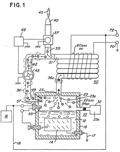 FIG. 2 is a magnetic particle tubing, in an electrical schematic circuit
arrangement, illustrating the induced direct and alternating current voltage.
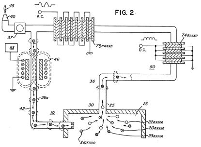 DETAILED DESCRIPTION OF DRAWINGS
Referring now to FIG. 1 there is illustrated the invention of the preferred
embodiment in a simplified schematic arrangement. The generator 10 comprises
an airtight pressure housing 15 of non-corrosive, non-oxydizing, non-reactive
material. The housing 15 is filled with natural water of a predetermined
level. Immersed in the water 12 is an array of plates 14.
In the preferred embodiment of the invention of FIG. 1, as disclosed
in my co-pending application Ser. No. 302,807, the plates 14 are in pairs
of similar non-corrosive, non-oxydizing, non-reactive material. A variable
voltage source 16 having circuitry to restrict the amperage comprises additionally
a pair of terminals connecting a positive and negative voltage to alternate
plates 14 in the pair. The applied potential to the plates causes the hydrogen
and oxygen atoms to disassociate themselves from the water molecule.
The released hydrogen gas depicted as particles 20a xxx 20n and oxygen
gas particles 22a xxx 22n are collected and stored in the chamber 23 together
with other released gasses such as nitrogen 21a xxx 21n.
The loop arrangement of tubing 50 has wound thereon a substantial number
of turns 60a xxx 60n in a winding 60. The number and size of the turns
is related to the tubing configuration and voltage/current output as setforth
in my co-pending application. The magnetically charged particles traveling
with a high accelerated velocity pass through the tubing 50. As the magnetically
charged particles pass through the core of the winding 60, their magnetic
field 36a traverses the windings 60a xxx 60n, and induces a voltage/current
therein. The output voltage/current is utilized via terminals 70-72.
As aforesaid, the storage chamber 23 is maintained at a predetermined
pressure; and once the pressure is attained the hydrogen/oxygen gasses
will be expelled into outlet line 25 with a substantial velocity. The pressure
released gas mixture continues through the entire loop arrangement of tubing
50.
Upon demand for the flame, (such as for heat) from demand circuit 65,
the valve 37 is opened causing the gas mixture circulating in closed loop
50 to be released to the nozzle 40 and provide the flame 45 upon ignition.
The hydrogen/oxygen gasses having the particles superimposed therein
will separate and be pressure released via tubing 35 to the nozzle 40.
In that the magnetic fields of the polarized particles provide an attractive
force, the motion of the polarized particles through the closed loop 50
will be greater than the gas mixture pressure release. That is, with the
valve 37 open the hydrogen/oxygen gasses will separate themselves from
the polarized particles. The hydrogen/oxygen gasses will go via 35 to nozzle
40 whereas the polarized particles will continue to circulate through the
closed loop. The chamber 23 further includes switch means 57 to shut off
the electrical source 16 to the generator system when the pressure in the
chamber 23 sensed by pressure gauge 55, achieves a predetermined level.
In the operation of the hydrogen generator as a burner, as disclosed
in the co-pending patent application Ser. No. 411,797, the outlet tube
25 is connected directly to the nozzle 40 to obtain the flame 45 upon ignition.
The operation of the gas burner is not altered in the present invention.
The housing 15 further comprises an inlet 34 having source 36 connected
thereto. This permits the entry into the chamber 23 of a substantial amount
of permanently polarized magnetized particles 36a xxx 36n.
The polarized particles 36a xxx 36n upon entry into the chamber 23 superimpose
themselves on the hydrogen/oxygen gasses.
Upon demand, as set forth below, the opening of the valve 37 causes
a pressure differential with the gasses collected in the chamber 23. In
this way the gasses having the polarized particles superimposed thereon
will be pressure released and caused to enter the closed loop 50.
Once in the closed loop the accelerator 45 will maintain the gasses
and the superimposed polarized particles in a continuous circulating motion
through the closed loop 50.
Connected to the outlet tubing 25 is a series of loops of non-magnetic
tubing 50. The tubing in its loop configuration can be any one of the arrangements
illustrated in my co-pending patent application, supra. The opposite end
51 of the loop 60 tubing is connected, via a Y connection, either to the
burner assembly 40, via line 35, or a return line 42 to the storage 30.
chamber 23.
It is to be appreciated that a miniscule amount of polarized particles
will be carried into the outlet 35 as well as hydrogen/oxygen gas continuing
to circulate through the closed loop. In the event the amount of polarized
particles expended should become significant, the quantity of particles
will be replenished from source 32.
Upon satisfaction of the demand, the valve 37 will close and thereby
cause the gas mixture circulating through closed loop 50 to return to the
collection chamber 23 via close loop line 42. In this arrangement the pump
45 will continue to be operative and cause a continuous circulation of
the polarized particles through the closed loop. If the gas in the collection
chamber is of the preset pressure, as sensed at gauge 55, the voltage via
terminal 16 will be cutoff discontinuing the generation of gas.
With hydrogen/oxygen gas mixture demand circuit quiescent, the polarized
particles will not be separated from the hydrogen/oxygen gasses at the
outlet 35. The pump 45 is a continuous pump and thereby continuous to circulate
through the closed loop 50 the polarized particles superimposed on the
gas mixture from chamber 23.
The magnetized particle source 32 is operative to transform a material
into minute vapor particles that are capable of being permanently polarized
magnetically. The vapor, in the nature of a gas will superimpose on the
hydrogen/oxygen gas.
With particular reference to FIG. 2 there is illustrated, partly in
schematic and partly pictorial the preferred embodiment of the invention.
Initially is is noted that the pump 45 of FIG. 1 has been replaced by
the electrical particle accelerator 46. The accelerator 46 is a non-mechanical/no
moving part element and therefore not subject to wear. It is to be recalled,
polarized particles have placed there on a magnetic field potential. Hence,
as the magnetized particles approach the accelerator 46 they are attracted
and as they pass the center of the accelerator and they are propelled therethrough.
Other propulsion means in lieu of the pump 45 of FIG. 1 or the accelerator
46 of FIG. 2 may be utilized.
As noted in the aforesaid co-pending patent application, the induced
current/voltage can be, at the ouput 70-72, either direct current, or alternating
current, or both. With reference to FIG. 2, the simplified schemetic illustrates
a direct current voltage 4 parallel winding and an alternating current
75 in serial winding.
The number of coils 74a xxx n of direct current windings of coil 74
will determine the ripple frequency of the direct current voltage and its
amplitude. Similarly, the number of alternating current windings 75a xxx
n will determine the alternating frequency of the alternating current voltage
and its amplitude.
More importantly, the aforesaid ripple frequency of the single polarity
voltage of coil 74 and alternating frequency of the alternating voltage
of coil 75 can be altered, varied, and controlled. That is, the frequency
is a function of the number of discrete windings of the coils times the
velocity of the gas per second. The velocity of the polarized particles
in tubing 50, in turn, is varied by varying the magnitude of the input
voltage to the accelerator 46. Simply an arithmetical increase in acceleration
of the polarized particles results in a geometrical increase in frequency
an amplitude of the ouput voltage from either the direct current winding
74 or the alternating current winding 75.
In the co-pending application, supra, for the Electrical Particle Generator,
the accelerator input voltage source 53 is intended to comprise circuitry
to provide alternate forms of electrical power, such as direct current,
alternating current, direct current pulsing, and variable voltage. The
output taken at the pick-up windings is related to the input voltage in
shape, magnitude and in waveform.
With reference to FIG. 1 and with continued reference to FIG. 2, the
hydrogen/oxygen generator 10, has applied to the plates 14 a direct current
voltage. The voltage applied to the plates 14 from power supply 16, depending
upon the utility of the generator, may be a variable voltage. For instance,
if it is desired to vary the intensity of the flame 45, the voltage at
the plates 14 will be varied.
Further, as specifically repeated, the voltage is current limited. Accordingly,
the power source 16 will provide circuitry for varying the voltage to the
plates 14 and for restricting the amperage to a neglible value relative
to said voltage.
In a self-sustaining embodiment of the gas electrical generator, a portion
of the output at the voltage taps 70-72 of the pick-up coils is directed
back to the power supply 16. In that the total power requested to be applied
to the plates 14 is relatively low, an insignificant portion of the ouput
at taps 70-72 is required for sustained operation of the generator.
The electrical particle portion of the electrical gas generator of the
present invention is operative continuously as set forth above. Hence the
output voltage at taps 70-72 will be available to the power supply 16 whenever
a demand for gas generation is made.
US Patent # 4,465,455
Start-up/Shut-down for a Hydrogen Gas Burner
Stanley Meyer
(August 14, 1984 )
Abstract ~
System for flame start-up/shut-down for a hydrogen gas mixture burner.
An electrical probe igniter positioned adjacent the gas port outlet. On
demand the igniter is actuated to heat and electrically heat a thermal
switch. Responsive electronic controls actuate the appropriate valves and
circuits for operational start-up. Upon the ignition of the generated hydrogen
gas mixture, a second thermal probe is heated by the flame to deactivate
the ignition and start-up circuits. After demand the second thermal probe
cools and the circuit is restored for start-up again. A safety probe positioned
in the flame is quiescent. In the event of demand time shut-down, the safety
probe will activate the circuits for restart. If failure to start-up continues
for a predetermined time, the safety probe circuit will effect permanent
shut-down.
Inventors: Stanley A. Meyer (3792 Broadway Blvd., Grove City, OH 43123)
Appl. No.: 422875
Filed: September 24, 1982
Current U.S. Class: 431/27; 431/66; 431/70; 431/78
Intern'l Class: F23N 005/00
Field of Search: 431/27,46,66,67,69-71,72,74,78-80 123/3,1 A,DIG.
12 204/129
References Cited [Referenced By]
U.S. Patent Documents
USP # 2,954,080 Sep., 1960 Prouty et al. 431/67.
3,086,583 Apr., 1963 Rerchow 431/46.
3,980,053 Sep., 1976 Horvath 123/3.
4,056,348 Nov., 1977 Wolfe 431/66.
Primary Examiner: Barrett; Lee E.
Attorney, Agent or Firm: Cennamo; Anthony D.
Description
CROSS REFERENCES
In the non-electrolysis process disclosed and claimed in my co-pending
patent application, Ser. No. 302,807, Filed: Sept. 16, 1981, For:HYDROGEN
GENERATOR SYSTEM, for separating hydrogen and oxygen atoms from water,
water is passed between two plates of similar non-oxidizing metal. The
one plate has placed thereon a positive potential and the other a negative
potential from a very low-direct-current power source. The sub-atomic action
of the direct current voltage causes the hydrogen and oxygen atoms to be
separated. The contaminants in the water are forced also to disassociate
itself and may be collected or utilized and disposed of. This in turn lends
the process to recombining the hydrogen and oxygen into pure water.
The direct current voltage applied to the plates is non-regulated and
non-filtered. The direct current acts as a static force on the water molecules;
whereas the rippling direct current voltage acts as a dynamic force. Pulsating
the direct current further acts as a dynamic force and enhances considerably
the splitting of the atoms from the water molecules. An increase in voltage
potential further increases the hydrogen output. Certain plate arrangements
and configurations with graphical illustration or relative efficiency are
disclosed.
In my co-pending patent application, Ser. No. 422,495, Filed: Sept.
24, 1982, For: PERIODIC FLUSH SYSTEM FOR NON-ELECTROLYSIS HYDROGEN GENERATOR,
there is disclosed control apparatus and electrical circuitry for periodically
shutting down the hydrogen generator for flushing out the accumulated contamianats.
The shut-down is in a sequential step-by-step operation. After the flushing
is complete, the hydrogen generator is started up and, again, in a sequential
step-by-step operation. Although the functions are numerous, the most critical
is the opening and closing of the gas valves, and the switching on and
off of the electrical circuitry to the exciter elements.
BACKGROUND
Heating and air environmental systems of the prior art have included
sensing systems for flame-out, power loss or the like. These systems do
provide some form of shut-down upon occurrence of a malfunction.
However, the prior art systems are either of gas, oil, or electrical.
Although a gas or oil furnace will utilize electrical circuitry for a blower,
the energy, whether gas, oil, or electric, is supplied either by a utility
or in bulk. None of the prior art systems generate the energy that is used
in the heating or air control system. Accordingly, no monitoring systems
for the generator systems are known in the prior art, that are applicable
heating or air control systems.
SUMMARY OF INVENTION
The present invention in its preferred embodiment provides a monitoring
system and a start-up/shut-down circuitry and apparatus for a hydrogen
gas burner. The system is distinctive in that the hydrogen generator is
a demand system; that is, hydrogen gas is generated only when the thermostat
(or other gauge) dictates the energy is needed. Accordingly, the start-up
is the start-up of the energy generating system and thereafter starting
the igniter to ignite the hydrogen gas mixture. Further, although the prior
systems start-up on demand; none have a need for periodic shut-down.
The present invention is a start-up/shut-down system for an energy generator
and for the utilization of the energy generated. The function in addition
to demand is periodic. Then, again, the same procedure is followed upon
the occurrence of malfunction.
The apparatus comprises an igniter in the flame path that upon actuation
heats a thermal probe that controls the electrical/electronic circuitry
for opening and closing the various controls and switches. Another probe
deactivates the ignition and start-up upon completing the function. A safety
probe positioned in the flame path is time controlled to start-up in the
occurrence of a flame-out, if failure occurs in the attempt to retract
within a given period of time the entire system is shut-down.
OBJECTS
It is a principal object of the present invention to provide a monitoring
and control system for start-up and shut-down of an energy generator system.
Another object of the present invention is to provide such a control
system that is operable upon demand, periodically operable, and operable
upon occurrence of a malfunction.
A further object of the invention is for a monitoring and control system
that distinguishes between an accidental flame-out and a flame-out caused
by malfunction of the system.
A further object of the invention is for a monitoring and control system
that provides a restart function upon accidental flame-out.
Other objects and features of the present invention will become apparent
from the following detailed description when taken in conjunction with
the drawings in which:
BRIEF DESCRIPTION OF DRAWINGS
FIG. 1 schematically depicts a preferred embodiment of the invention
of a hydrogen gas mixture burner incorporating the features of the invention.
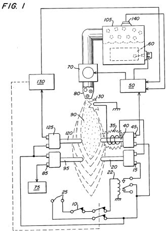 FIG. 2 is a schematic block diagram of the preferred embodiment in a complete
operational generator system.
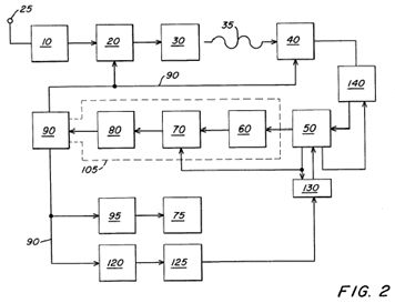 DETAILED DESCRIPTION OF DRAWINGS
With reference to FIG. 1 there is a illustrated schematically the mechanical/electrical
apparatus of the system of the preferred embodiment of the invention taken
in conjunction with the hydrogen generator of my co-pending patent application,
supra. In FIG. 2 the electrical circuitry and actuating valves and the
like are depicted in a sequential schematic block type of arrangement.
Referring to FIG. 1, together with FIG. 2, the preferred embodiment
of the present invention may now be described. The thermal probe switch
20, before start-up, is in a normally closed position. Upon the demand
for energy, dictated by the thermostat 10 control, the relay 22 is closed,
applying electrical power from source 25 to the electrical spark igniter
30 through the closed thermal probe 20. Upon the spark igniter 30 attaining
the appropriate temperature, the radiant heat from coil 35 heats the thermal
probe 40.
As the thermal probe 40 heats, the normally open switch 45 closes and
in turn actuates the electrical control circuit 50. The control circuit
50 closes the circuit to apply electrical power to the exciters 60 in the
non-electrolysis hydrogen generator 105.
In sequence, and upon attaining appropriate pressure from the gasses
generated as indicated by pressure valve in the hydrogen generator 105,
also illustrated in FIG. 2 in dotted line block, the gas outlet valve 70
is opened, permitting gas to be expelled through a nozzle assembly 80.
Upon the gas making contact with the heated electrical spark igniter
30, the hydrogen gas mixture, expelled from the controlled port opening
in nozzle assembly 80 is ignited into a continuous extremely high temperature
flame 90.
The thermal probe 95 immediately begins to heat and after attaining
the predetermined temperature the fan assembly 75 is actuated by the closure
of relay 85.
The flame 90 having been ignited and burning, causes the thermal probe
20 to become heated and thereby opening its relay 15. In turn, the voltage
applied to the electrical spark igniter 30 is terminated by the open relay
15.
Upon the demand from the thermostat 10 being reached the relay 22 is
opened thereby cutting off the voltage 25 to the thermal probe switch 20.
Sequentially the electrical control circuit 50 opens the circuit providing
voltage to the exciters 60; thereby shutting gas outlet valve 70 to terminate
the flame 90. Thereafter the circuit is ready for start-up again upon demand
from the thermostat 10, as aforesaid.
A safety probe 120 is also positioned in the flame 90. During operation
of the system under demand from the thermostat control 10, the probe 120
will remain heated. In this condition the attendant relay 130 is inoperative.
If for some reason the flame 90 should be extinguished during the demand
period the safety probe 120 will quickly cool and in sequence the attendant
relay 130 will open. Relay 130 connected to relay 22 in the power circuit
will act in place of the demand thermostat 10, that is, the relay 130 will
override the demand thermostat 10. The circuits and functions will follow
as above-described for start-up in the event the flame-out was accidental.
The safety control system further includes a timer circuit and thermostat
125 that will permit the probe 120 to attain its temperature within a given
period of time. If the probe 120 does not attain its temperature the same
start-up procedure will follow again, within a given period of time. The
timer 125 is so set that unless the probe 120 attains the appropriate temperature
within the given period of time the entire circuitry is shut down permanently.
This denotes a major failure in the system and not a simple flame-out.
Finally, in the unlikely event of pressure build-up upon malfunction,
there is provided a safety relief valve 140.
USP 4,421,474
Hydrogen Gas Burner
Stan Meyer
Abstract ~
A hydrogen gas burner for the mixture of hydrogen gas with ambient air
and non-combustible gasses. The mixture of gasses when ignited provides
a flame of extremely high, but controlled intensity and temperature. The
structure comprises a housing and a hydrogen gas inlet directed to a combustion
chamber positioned within the housing. Ambient air intake ports are provided
for adding ambient air to the combustion chamber for ignition of the hydrogen
gas by an ignitor therein. At the other end of the housing there is positioned
adjacent to the outlet of the burner (flame) a barrier/heating element.
The heating element uniformly disperses the flame and in turn absorbs the
heat. The opposite side to the flame, the heating element uniformly disperses
the extremely hot air. A non-combustible gas trap adjacent to the heating
element captures a small portion of the non-combustible gas (burned air).
A return line from the trap returns the captured non-combustible gas in
a controlled ratio to the burning chamber for mixture with the hydrogen
gas and the ambient air.
Description ~
CROSS REFERENCE
The hydrogen/oxygen generator utilized in the present invention is that
disclosed and claimed in my co-pending patent application, Ser. No.: 302,807,
filed: Sept. 16, 1981, for: HYDROGEN GENERATOR SYSTEM. In that process
for separating hydrogen and oxygen atoms from water having impurities,
the water is passed between two plates of similar non-oxidizing metal.
No electrolyte is added to the water. The one plate has placed thereon
a positive potential and the other a negative potential from a very low
amperage direct-current power source. The sub-atomic action of the direct
current voltage on the non-electrolytic water causes the hydrogen and oxygen
atoms to be separated--and similarly other gasses entrapped in the water
such as nitrogen. The contaminents in the water that are not released are
forced to disassociate themselves and may be collected or utilized and
disposed of in a known manner.
The direct current acts as a static force on the water molecules; whereas
the non-regulated rippling direct current acts as a dynamic force. Pulsating
the direct current further enhances the release of the hydrogen and oxygen
atoms from the water molecules.
In my co-pending patent application, Ser. No.: 262,744, filed: May 11,
1981, for: HYDROGEN AIRATION PROCESSOR, there is disclosed and claimed
the utilization of the hydrogen/oxygen gas generator. In that system, the
burn rate of the hydrogen gas is controlled by the controlled addition
of non-combustible gasses to the mixture of hydrogen and oxygen gasses.
PRIOR ART
The electrolysis process for generating hydrogen and oxygen gas is well
known in the art. It is, of course, further understood with a proper mixture
of oxygen gas, the hydrogen gas is combustible and under ideal conditions
a flame, may be had. Reference is made to U.S. Pat. No. 4,184,931. However,
in that the burning velocity of hydrogen is 265-325 cm./sec. versus 37-45
cm./sec. of that of gasoline, the velocity of hydrogen is so great that
the hydrogen ensuing from a nozzle will not under ordinary circumstances
sustain a flame.
Therefore, to sustain a flame at a nozzle attached to a hydrogen generator
the burning velocity of the hydrogen gas must be reduced.
It has been found that all water in its natural state whether it be
tap water, well water, sea water, or fresh water is a saturate of ambient
air. Further, in that ambient air contains a substantial amount of nitrogen,
all natural water will have entrapped therein nitrogen. Again, the percentage
of nitrogen entrapped in natural water has been determined to be a fixed
percentage and very uniform at seventeen (17%) percent -- irrespective
of the source of the water or its impurities. Hence, a natural water gas
analysis will show a seventeen percent of nitrogen relative to the hydrogen
and the oxygen.
The nozzle connected to the collection chamber via an appropriate line,
has a port opening of a controlled size and configuration, related to the
size of the flame and the temperature and velocity of the burning gas mixture.
To maintain the flame, that is to prevent blowout, additional nozzles are
included when the overall flame size is to be increased.
SUMMARY OF INVENTION
The present invention is for a hydrogen gas burner and comprises a combustion
chamber for the mixture of hydrogen gas, ambient air, and non-combustible
gasses. The mixture of gasses is ignited and burns at a retarded velocity
rate and temperature from that of hydrogen gas, but at a higher temperature
rate than other gasses.
The extremely narrow hydrogen gas mixture flame of very high temperature
is restricted from the utilization means by a heat absorbing barrier. The
flame strikes the barrier which in turn disperses the flame and absorbs
the heat therefrom and thereafter radiates the heat as extremely hot air
into the utilization means.
Positioned on the opposite side of the heat radiator/barrier is a hot
air trap. A small portion of the radiated heat is captured and returned
to the combustion chamber as non-combustible gasses. Valve means in the
return line regulates the return of the non-combustible gas in a controlled
amount to control the mixture.
The present invention is principally intended for use with the hydrogen
generator of my co-pending patent application, supra; but it is not to
be so limited and may be utilized with any other source of hydrogen gas.
OBJECTS
It is accordingly a principal object of the present application to provide
a hydrogen gas burner that has a temperature controlled flame and a heat
radiator/barrier.
Another object of the present invention is to provide a hydrogen gas
burner that is capable of utilizing the heat from a confined high temperature
flame.
Another object of the present invention is to provide a hydrogen gas
burner that is retarded from that of hydrogen gas, but above that of other
gasses.
Another object of the present invention is to provide a hydrogen gas
burner that utilizes the exhaust air as non-combustible gas for mixture
with the hydrogen gas.
Another object of the present invention is to provide a hydrogen gas
burner that is simple but rugged and most importantly safe for all intended
purposes.
Other objects and features of the present invention will become apparent
from the following detailed description when taken in conjunction with
the drawings in which:
BRIEF DESCRIPTION OF DRAWINGS
FIG. 1 is an overall crossectional view of the present invention in
its most preferred embodiment.
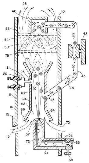 FIG. 2 is a graphical illustration of the burning of various standard fuels
with that of hydrogen velocities.
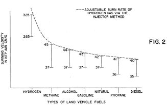 DETAILED DESCRIPTION OF INVENTION
With particular reference FIG. 1 there is illustrated in a schematic
crossection the principals of the present invention.
The structure of the preferred embodiment comprises a housing 10, having
an igniter 20 extending through the wall 11 thereof. A combustion chamber
60 positioned within the housing 10 has a first open end 62. A hydrogen
gas 72 inlet 30 directs hydrogen gas via port 37 from a source 35 to the
inlet 62 of the combustion chamber 68. Also directed to the same inlet
62, and assisted by flanges 64 and 66, is ambient air 70 entering through
ports 13 in the housing 10.
Adjacent the opposite end of the combustion chamber 60 the gas mixture
75 is ignited by the ignitor 20 to produce flame 77.
The velocity of the flame 77 causes it to strike and penetrate the barrier/radiator
50. The barrier 50 is of a material, such as metallic mesh or ceramic material,
to disperse therein the flame and in turn become saturated with heat. The
flame 77 is of a size sufficient to be dispersed throughout the barrier
50, but yet, not penetrate through the barrier 50.
Radiated from the surface 52 of the barrier 50 is superheated air 56
(gasses) to be passed on to a utilization device.
Adjacent to surface 52 of barrier/radiator 50 is a hot air trap 40 with
closed loop line 45 returning non-combustible gas 44 to the combustion
chamber 60. Control valve 42 is intermediate the line 45.
In operation of the preferred embodiment hydrogen gas, 72, emitted from
the nozzle 37 is directed to the combustion chamber 60. The flanges 64
and 66 on the open end of housing 63 of the combustion chamber 60 enlarges
the open end of 62. In the enlargement ambient air from the opening 13
in the housing 10 is also directed to the combustion chamber 60.
The ambient air and hydrogen traverses the opening 43 and further mixes
with the non-combustible gas 44 from the closed loop line 45 with the hot
air trap 40.
The mixture of hydrogen gas 72, ambient air 70, and non-combustible
gas 44, is ignited by the ignitor 20 having electrical electrodes 21 and
23. Upon ignition flame 77 ensues.
The mixture is controlled with each of three gasses. That is, the line
32 from the hydrogen source 35 has a valve 38 therein for controlling the
amount of hydrogen 72 emitted from the nozzle 37. The opening 13 has a
plate adjustment 15 for controlling the amount of ambient air 60 directed
to the combustion chamber 60, and the closed-loop line has valve 42, as
aforesaid, for controlling the amount of non-combustible gasses in the
mixture.
It can be appreciated that the temperature of the flame 77 and the velocity
of the flame 77 is a function of the percentage of the various gasses in
the mixture. In a practical embodiment, the flame 70 temperature and velocity
was substantially retarded from that of a hydrogen flame per se; but yet,
much greater than the temperature and velocity of the flame from the gasses
utilized in a conventional heating system.
To maintain a sufficient pressure for combustion of the hydrogen gas
mixture with a minimum of pressure (for safety) and to limit blowout, the
nozzle 37 opening 39 is extremely small. As a consequence, if the hydrogen
gas were burned directly from the nozzle 37, the flame would be finite
in diameter. Further, its velocity would be so great it is questionable
whether a flame could be sustained.
The mixing of ambient air and non-combustible gas does enlargen the
flame size and does reduce its velocity. However, to maintain a flame higher
in temperature and velocity than the conventional gasses, the size and
temperature of the flame is controlled by the aforementioned mixture.
Therefore, to utilize the flame 77 in a present day utilization means,
the flame is barred by the barrier 50. The barrier 50 is of a material
that can absorb safely the intense flame 77 and thereafter radiate heat
from its entire surface 52. The material 54 can be a ceramic, metallic
mesh or other heat absorbing material known in the art. The radiated heat
56 is directed to the utilization means.
As aforesaid, the mixture of gasses that are burned include non-combustible
gasses. As indicated in the above-noted co-pending patent applications,
an excellent source of non-combustible gasses are exhaust gasses. In this
embodiment, the trap 50 entraps the hot air 74 and returns the same, through
valve 42, to the combustion chamber 60 as non-combustible gas.
With reference to FIG. 2 there is illustrated the burning velocity of
various standard fuels. It can be seen the common type of fuel burns at
a velocity substantially less than hydrogen gas.
The ratio of hydrogen with non-combustible oxygen gasses is varied to
obtain optimum burning velocity and temperature for the particular utilization.
Once this is attained, the ratio, under normal conditions, will not be
altered. Other uses having different fuel burn temperature and velocity
will be adjusted in ratio of hydrogen/oxygen to non-combustible gasses
in the same manner as exemplified above.
Further, perhaps due to the hydrogen gas velocity, there will occur
unburnt gas at the flame 77 output. The barrier 50, because of its material
makeup will retard the movement and entrap the unspent hydrogen gas. As
the superheated air 77 is dispersed within the material 54, the unspent
hydrogen gas is ignited and burns therein. In this way the barrier 50 performs
somewhat in the nature of an after burner.
USP # 4,389,981
Hydrogen Gas Injector System for Internal Combustion
Engine
Stan Meyer
Abstract ~
System and apparatus for the controlled intermixing of a volatile hydrogen
gas with oxygen and other non-combustible gasses in a combustion system.
In a preferred arrangement the source of volatile gas is a hydrogen source,
and the non-combustible gasses are the exhaust gasses of the combustion
system in a closed loop arrangement. Specific structure for the controlled
mixing of the gasses, the fuel flow control, and safety are disclosed.
Description ~
CROSS REFERENCES AND BACKGROUND
There is disclosed in my co-pending U.S. patent application Ser. No.
802,807 filed Sept. 16, 1981 for a Hydrogen-Generator, a generating system
converting water into hydrogen and oxygen gasses. In that system and method
the hydrogen atoms are disocciated from a water molecule by the application
of a non-regulated, non-filtered, low-power, direct current voltage electrical
potential applied to two non-oxidizing similar metal plates having water
passing there-between. The sub-atomic action is enhanced by pulsing the
non-regulated and non-filtered direct current voltage. The apparatus comprises
structural configurations in alternative embodiments for segregating the
generated hydrogen gas from the oxygen gas.
In my co-pending patent application filed May 5, 1981, U.S. Ser. No.
262,744 now abandoned for Hydrogen-Airdation Processor, non-volatile and
non-combustible gasses are controlled in a mixing stage with a volatile
gas. The hydrogen airdation processor system utilizes a rotational mechanical
gas displacement system to transfer, meter, mix, and pressurize the various
gasses. In the gas transformation process, ambient air is passed through
an open flame gas-burner system to eliminate gasses and other present substances.
Thereafter the non-combustible gas-mixture is cooled, filtered for impurity
removal, and mechanically mixed with a pre-determined amount of hydrogen
gas. There results a new synthetic gas. The synthetic gas formation stage
also volume meters and determines the proper gas-mixing ratio for establishing
the desired burn-rate of hydrogen gas. The rotational mechanical gas displacement
system in that process determines the volume-amount of synthetic gas to
be produced.
The above-noted hydrogen airdation processor, of my co-pending application,
is a multi-stage system having utility in special applications. Whereas
the hydrogen generator system of my other mentioned co-pending application
does disclose a very simple and unique hydrogen generator.
In my co-pending patent application Ser. No. 315,945, filed Oct. 18,
1981 there is disclosed a combustion system having utility in a mechanical
drive system. Particularly in one instance to drive a piston in an automotive
device. There is shown a hydrogen generator for developing hydrogen gas,
and perhaps other non-volatile gasses such as oxygen and nitrogen. The
hydrogen gas with the attendant non-volatile gasses are fed via a line
to a controlled air intake system. The combined hydrogen, non-volatile
gasses, and the air after inter-mixing are fed to a combustion chamber
where it is ignited. The exhaust gasses of the combustion chamber are returned
in a closed loop arrangement to the mixing chamber for the mixture of volatile
and non-combustible gasses. Particular applications and structural embodiments
of the system are disclosed.
SUMMARY OF INVENTION
The system of the present invention in its most preferred embodiment
is for a combustion system utilizing hydrogen gas; particularly to drive
a piston in an automobile device. The system utilizes a hydrogen generator
for developing hydrogen gas. The hydrogen gas and other non-volatile gasses
are fed to a mixing chamber also having oxygen fed thereto. The mixture
is controlled to regulate the burning temperature; that is, to lower the
temperature velocity of the hydrogen gas to that of the commercial fuels.
The hydrogen gas feed line to the combustion chamber includes a fine linear
control gas flow valve. An air intake is the source of oxygen and it also
includes a variable valve. The exhaust gasses from the combustion chamber
are utilized in a controlled manner as the non-combustible gasses.
The hydrogen generator is improved upon to include a holding tank to
provide a source of start-up fuel. Also, the hydrogen gas generator includes
a switch to the power source operable from one position to another dependant
upon a pressure sensing switch on the combustion chamber.
The simplified structure includes a series of one-way valves, safety
valves, and quenching apparatus. The combination of apparatus comprises
the complete assembly for converting the standard automobile engine from
gasoline (or other fuels) to the hydrogen gas mixture.
OBJECTS
It is accordingly a principal object of the present invention to provide
a combustion system of gasses combined from a source of hydrogen and non-combustible
gasses.
Another object of the invention is to provide such a combustion system
that intermixes the hydrogen and non-combustible gasses in a controlled
manner and thereby control the combustion temperature.
A further object of the invention is to provide such a combustion system
that controls the fuel flow to the combustion chamber in s system and apparatus
particularly adapted to hydrogen gas.
Still other objects and features of the present invention will become
apparent from the following detailed description when taken in conjunction
with the drawings in which:
BRIEF DESCRIPTION OF DRAWINGS
FIG. 1 is a mechanical schematic illustration partly in block form of
the present invention in its most preferred embodiment.
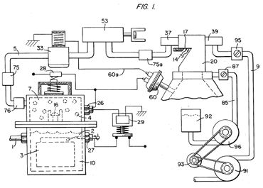 FIG. 2 is a block schematic illustration of the preferred embodiment of
the hydrogen injector system of FIG. 1.
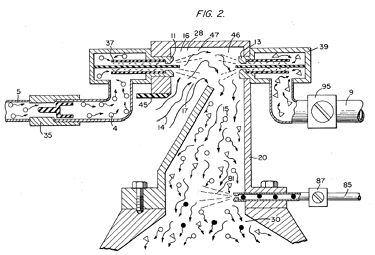 FIG. 3 is the fine linear fuel flow control shown in FIG. 1.
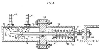 FIG. 4 is crossectional illustration of the complete fuel injector system
in an automobile utilizing the concepts of the present invention.
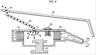 FIG. 5 is a schematic drawing in a top view of the fuel injector system
utilized in the preferred embodiment.
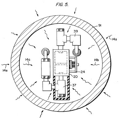 FIG. 6 is a crossectional side view of the fuel injector system in the
present invention.
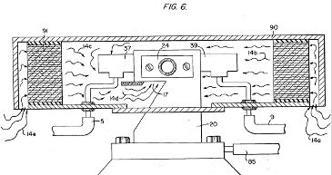 FIG. 7 is a side view of the fuel mixing chamber.
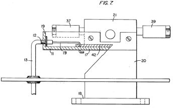 FIG. 8 is a top view of the air intake valve to fuel mixing chamber.
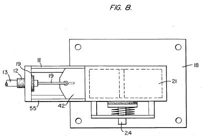
FIG. 9 is a comparison of the burning velocity of hydrogen with respect
to other fuels.
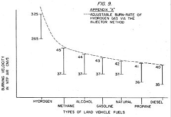 DETAILED DESCRIPTION OF INVENTION TAKEN WITH DRAWINGS
Referring to FIG. 1 the complete overall gas mixing and fuel flow system
is illustrated together for utilization in a combustion engine particularly
an engine utilized in an automobile.
With specific reference to FIG. 1, the hydrogen source 10 is the hydrogen
generator disclosed and described in my co-pending application, supra.
The container 10 is an enclosure for a water bath 2. Immersed in the water
2 is an array of plates 3 as further described in my co-pending application,
supra. Applied to plates 3 is a source of direct current potential via
electrical inlet 27. The upper portion 7 of the container 10 is a hydrogen
storage area maintaining a predetermined amount of pressure. In this way
for start up there will be an immediate flow of hydrogen gas. To replenish
the expended water the generator provides a continuous water source 1.
Thereafter, the generator is operable as described in the aforesaid patent
application.
The safety valve 28 is rupturable upon excessive gas build-up. Whereas
the switch 26 is a gas pressure switch to maintain a predetermined gas
pressure level about a regulated low-volume.
The generated hydrogen gas 4 is fed from the one-way check valve 16
via pipe 5 to a gas mixing chamber 20, wherein the hydrogen gas is inter-mixed
with non-combustible gasses via pipe line 9 from a source hereinafter described.
In the event one way valve 75 should fail and there be a return spark
that might ignite the hydrogen gas 4 in the storage area 7 of hydrogen
generator 10, quenching assembly 76 will quench the spark and prevent such
ignition.
With particular reference to FIG. 2 the hydrogen gas via pipe line 5
and non-combustible gasses via pipe line 9 are fed to a carburator (air-mixture)
system 20 also having an ambient air intake 14.
The hydrogen gas 4 is fed via line 5 through nozzle 11 in a spray 16
in to the trap area 46 of the mixing chamber 20. Nozzle 11 has an opening
smaller than the plate openings in the quenching assembly 37, thereby preventing
flash back in the event of sparking. The non-volatile gasses are injected
into mixing chamber 20 trap area 47 in a jet spray 17 via nozzle 13. Quenching
assembly 39 is operable much in the same manner as quenching assembly 37.
The ambient air is, in the preferred arrangement, the source of oxygen
necessary for the combustion of the hydrogen gas. Further, as disclosed
in the aforesaid co-pending application the non-volatile gasses are in
fact the exhaust gasses in a closed loop system. It is to be understood
that the oxygen and/or the non-combustible gasses can be from an independant
source.
With continued reference to FIG. 2 the gas trap area 47 is a predetermined
size. In that hydrogen is lighter than air, the hydrogen will rise and
become entrapped in the are 47. The size of area 47 is sufficient to contain
enough hydrogen gas for instant ignition upon start up of the combusiton
engine.
It will be noted that the hydrogen gas is injected in the uppermost
region of the trap area 47. Hydrogen rises at a much greater velocity than
oxygen or non-combustible gasses; perhaps three times or greater. Therefore,
if the hydrogen gas entered the trap area 47 (mixing area) at its lowermost
region the hydrogen gas would rise so rapidly that the air could not mix
with the oxygen. With the structure shown in FIG. 2 of the trap area 47,
the hydrogen gas is forced downwardly into the air intake 15. That is,
the hydrogen gas is forced downwardly into the upwardly forced air and
readily mixed therewith.
The ratio of the ambient air (oxygen) 14 and the non-combustible gas
via line 9 is a controlled ratio and determined by the particular engine.
Once the proper combustion rate is determined by the adjustment of valve
95 for varying the amount of the non-combustible gas and the adjustment
of valve 45 for varying the amount of the ambient air, the ratio is maintained.
In a system wherein the non-combustible gasses are the exhaust gasses
of the engine in a closed loop-arrangement, and wherein the air intake
is under the control of the engine, the flow velocity and hence the air/non-combustible
mixture, is maintained by the acceleration of the engine.
The mixture of air with non-combustible gasses becomes the carrier for
the hydrogen gas. That is, the hydrogen gas is superimposed on the air/non-combustible
mixture. By varying the amount of hydrogen gas superimposed on the air/non-combustible
mixture, the r.p.m. of the engine is controlled.
Reference is made to FIG. 3 illustrating precisely in a side view crossection
the fine linear fuel flow control 53. The hydrogen gas 4 enters chamber
43 via gas inlet 41. The hydrogen gas passes from chamber 43. The hydrogen
gas passes from chamber 43 to chamber 47 via port or opening 42. The amount
of gas passing form chamber 43 to chamber 47 is controlled by controlling
the port opening 42.
The port opening is controlled by the insertion there through the linearly
tapered pin 73. The blunt end of pin 73 is fixed to rod 71. Rod 71 passed
by supporting O-ring 75, through opening 81 in housing 30, to manual adjustment
mechanism 83.
The spring 49 retains the rod 71 is a fixed position relative to the
pin 73 and opening 42. Upon actuating the mechanism 83, the pin 73 will
recede from the opening 42 there by increasing the amount of gas passing
from chamber 43 to chamber 47.
The stops 67 and 69 maintain spring 49 in its stable position. The position
of the pin 73 in a fixed position relative to opening 42 is adjusted via
threaded nuts 63 and 67 on threaded rod 61. That is, the threaded adjustment
controls the idle speed or permits the minimum amount of gas to pass from
chamber 43 to chamber 47 for continuous operation of the combustion engine.
Referring now to FIG. 8 there is illustrated the air adjustment control
for manipulating the amount of air passing into the mixing chamber 20.
The closure 21 mounted on plate 18 has an opening 17 on end 11 thereof.
Slideably mounted over said opening 17 is a plate control 42. The position
of the plate relative to the opening 17 is controlled by the position of
the control rod 19 passing through a grommet 12 to control line. In event
of malfunction that may cause combustion of gasses in mixing chamber 20,
release valve 24 will rupture.
With reference now to FIG. 4, in the event hydrogen gas 4 should accumulate
in the mixing chamber 20 to excessive pressure, an escape tube 36 connected
to a port 34 on the automobile hood 32 permits the excess hydrogen gas
to safely escape to the atmosphere. In the event of a malfunction that
may cause combustion in the mixing chamber 20, the pressure relief valve
33 will rupture expelling hydrogen gas without combustion.
In the constructed arrangement of FIG. 1, there is illustrated a gas
control system that may be retrofitted to an existing automobile internal
combustion engine without changing or modifying automobile's design parameters
or characteristics.
The flow of the hydrogen volatile gas is, of course, critical; therefore,
there is incorporated in line 5 a gas flow valve 53 (FIG. 1) to adjust
the hydrogen flow. Gas flow valve is described in detail with reference
to FIG. 3.
The intake air 14 may be in a carburator arrangement with an intake
adjustment 55 that adjusts the plate 42 opening and also more fully described
with reference to FIG. 8.
To maintain constant pressure in hydrogen gas storage 7 in the on-off
operation of the engine, the gas flow control valve is responsive to the
electrical shut-off control 33. The constant pressure permits an abundant
supply of gas on start up and during certain periods of running time in
re-supply.
The switch 33 is in turn responsive to the vacuum control switch 60.
During running of the engine vacuum will be built up which in turn leaves
switch 33 open by contact with vacuum switch 60 through lead 60a. When
the engine is not running the vacuum will decrease to zero and through
switch 60 will cause electrical switch 33 to shut off cutting off the flow
of hydrogen gas to the control valve 53.
As low-voltage direct current is applied to safety valve 28, solenoid
29 is activated. The solenoid applies a control voltage to the hydrogen
generator exciter 3 via terminal 27 through pressure switch 26. As the
electrical power activates electric solenoid 29, hydrogen gas is caused
to pass through flow adjustment valve 16 and then outlet pipe 5 for utilization.
The pressure differential hydrogen gas output to gas mixing chamber 20
is for example 30 lbs. to 15 lbs. Once hydrogen generator 10 reaches an
optimum gas pressure level, pressure switch 26 shuts off electrical power
to the hydrogen excitors. If the chamber pressure exceeds a predetermined
level, the safety release valve 28 is activated disconnecting the electrical
current and thereby shutting down the entire system for safety inspection.
With particular reference now to FIG. 6 there is illustrated the fuel
injector system in a side crossectional view and to FIG. 5 in a top view.
The structural apparatus incorporated in the preferred embodiment comprises
housing 90 having air intakes 14a and 14e. The air passes through filter
91 around the components 14b and 14c and then to intake 14d of the mixing
chamber 20. The hydrogen enters via line 5 via quenching plates 37 and
into the mixing chamber 20. The non-volatile gasses pass via line 9 to
the quenching plates 39 and into the mixing chamber 20.
FIG. 7 illustrates the mechanical arrangement of components comprising
the overall structure of the mixing chamber 20 and shown independantly
in the other figures.
Returning to FIG. 1 there is illustrated the non-volatile gas line 9
passing through mixture pump 91 by engine pulley 93. Valve 95 controls
the rate of flow.
Also driven by pulley 93 is pump 96 having line 85 connected to an oil
resevoir 92 and valve 87 and finally to mixing chamber 20. As a practical
matter, such as in a non-oil lubricated engine, lubricating fluid such
as oil 81 is sprayed in the chamber 20, via oil supply line 85 for lubrication.
There has been several publications in the past year or so delving on
the properties of Hydrogen gas, its potential use, generating systems,
and safety. One such publication is "Selected Properties of Hydrogen" (Engineering
Design Data) issued February 1981 by the National Bureau of Standards.
These publications are primarily concerned with the elaborate and costly
processes for generating hydrogen. Equally so, they are concerned with
the very limited use of hydrogen gas because of its extremely high burning
velocities. This in turn reflects the danger in the practical use of hydrogen.
With reference to the graph of the Appendix A, it is seen that the burning
velocities of alcohol, propane, methane, gasoline, natural gas, and diesel
oil are in the range of minimum 35 to maximum 45. Further, the graph illustrates
that the burning velocity of hydrogen gas is in the range of 265 minimum
to 325 maximum. In simple terms in the order of 7.5 times the velocity
of ordinary commercial fuels.
Because of the hydrogen gas unusually high burning velocity, hydrogen
gas has been ruled out, by these prior investigators as a substitute fuel.
Furhter, even if an engine could be designed to accomodate such high velocities,
the danger of explosion would eliminate any thoughts of commercial use.
The present invention, as above described, has resolved the above-noted
criterea for the use of hydrogen gas in a standard commercial engine. Primarily,
the cost in the generation of hydrogen gas, as noted in the aforementioned
co-pending patent applications, is most minimal. Water with no chemicals
or metals is used. Also, as note in the aforementioned co-pending patent
applications, is the reduction in the hydrogen gas velocity. These co-pending
applications not only teach the reduction in velocity, but teach the control
of the velocity of the hydrogen gas.
In the preferred embodiment, practical apparatus adapting the hydrogen
generator to a combustion engine is described. The apparatus linearly controls
the hydrogen gas flow to a mixing chamber mixing with a controlled amount
of non-combustible gas oxygen, hence, the reduction in the hydrogen gas
velocity. The reduction in the hydrogen gas velocity makes the use of hydrogen
as safe as other fuels.
In more practical terms the ordinary internal combustion engine of any
size or type of fuel, is retrofitted to be operable with only water as
a fuel source. Hydrogen gas is generated from the water without the use
of chemicals or metals and at a very low voltage. The burning velocity
of the hydrogen gas has been reduced to that of conventional fuels. Finally,
every component or step in the process has one or more safety valves or
features thereby making the hydrogen gas system safer than that of conventional
automobiles.
In the above description the terms non-volatile and non-combustile were
used. It is to be understood they are intended to be the same; that is,
simply, gas that will not burn.
Again, the term storage has been used, primarily with respect to the
hydrogen storage area 7. It is not intended that the term "storage" be
taken literally--in fact it is not storage, but a temporary holding area.
With respect to area 7, this area retains a sufficient amount of hydrogen
for immediate start-up.
Other terms, features, apparatus, and the such have been described with
reference to a preferred embodiment. It is to be understood modifications
and alternatives can be had without departing from the spirit and scope
of the invention.
Molecular Dissociation of Water:
A Project for the Experimenter
by Dan Danforth
In. the original setup that Stan Meyer showed us, he used 36 volts as
the basic potential applied to the reaction chamber. He also commented
that stainless steel ( 410 not 403 ) was the only metal that could be used
as oxides formed with all others. His original chamber used 18 inch long
by 0.375 inch diameter (o.d.) rod surrounded by 1 inch diameter (i.d.)
16 inch long pipe. The reason for the difference in length is for mechanical
ease of construction. My prototype used 14 inch long rod and 12 inch long
pipe of similar diameters as the drawing indicates.
Having a severe lack of parts diversity here in Sri-Lanka, I was only
able to obtain a 24 volt. 8 amp transformer and built my circuitry around
that. The final output is 20 volts with Ml reading 10 amps to the pulsing
circuit which generates a symetricel squarewave ( 50% duty cycle ) to the
flyback inductor connected in series with the chamber as the schematic
shows. The flyback high voltage spike is directed across the chamber via
c* end d*. The use of a high voltage spike alone, without the current being
delivered through the liquid, will not cause the disassociation to take
place. This I verified using an ignition coil in place of the inductor
and applied the secondary with halfwave rectification and blocking capacitor
to prevent burn out to the chamber with no results. Apparently the current
in the water aligns the molecules approprately to allow the high voltege
spike to do its workr which in my opinion is the stimulation of molecular
resonance. Once Stan's unit was made to begin breakdown (which takes 6
to 8 seconds) he was able to reduce both current and voltage to miniscule
proportions. I attribute this to sympathetic oscillation of the aligned
molecules, requiring very little in the way of additional excitation. A
phenomena akin to Tesla's super resonance... resulting in Stan discovering
that he only had to supply three pulses in ten to satisfy the requirement
of the chamber. I have not yet had the opportunity to duplicate this portion
of the experiment but, in time I vill.
Duplication of the device described in these pages, however, will produce
the phenomena and hopefully launch other enterprising end inventive souls
on to designing their own refined models. It would be nice to have feedback
so that we can all collectively work to bring about the transition to non-pollution
energy.
P.S.- Though electrical circuit is by no means optinised, but represents
instead the result of parts availability here. Any good technician could
improve on it quite readily.
There are two primary frequencies that produce the best results. They
are: 14,372 Hz and 43,430 Hz. The former is about 50% more efficient, but
it seems that just about any frequency between 9 KHz and 143,762 KHz works
quite well. (1) This is because the nature of the wave form ( a spike )
is rich in harmonics and one of them is bound to be close to one of the
two primary frequencies.
Use of permanent magnets may also increase efficiency. I'll give you
the outcome of that attempt in my next letter along with the plans for
what I hope to be a much improved version.
Note: Sub-harmonics of the two primary frequencies at which dissociation
will occur:
43430
Hz
143762 HZ
SUBHARMONIC
SUBHARMONIC
1st 21715 HZ
1st 71881 HZ
2nd 14476.67 HZ
2nd 47920.67 HZ
3rd 15517.5 HZ
3rd 35840.1 HZ
4th
8686
4th 28752.4 HZ
*1500 VOLTS IS THE MINIMUM REQUIRED FOR MOLECULAR RINGING TO BEGIN.
Source publication: Unknown... Scanned from very bad photocopy.
Excerpts from Water Fuel Cell News Release # 4 (Winter/Spring
87/88)
"The Birth of New Technology: The Hydrogen Fracturing
Process & Related Water Fuel Cell Technology"
by Marcia Thompson
The purpose of establishing the Hydrogen Fracturing technology which
ahs been developed is to use energy from the atom to produce a system which
would lend itself to mass production. Meyer is now in the process of integrating
the Electrical Polarization Generator (EPG) into the Hydrogen Fracturing
Process. The Electrical Polarization Generator is in essence a gas battery
which produces electric energy directly from the fuel cell gases without
chemical interaction. The significance of the voltage is that it is a potential
energy source, not consumed energy. The most significant point is that
the influence of voltage has a phenomenal effect on the splitting of the
water molecule and does it in a controlled state. Voltage from the Electrical
Polarization Generator separates the water molecule economically by not
consuming power. It's a new technology --- bringing the water molecule
from a liquid to gas ionization state, which in turn sets up the Hydrogen
Fracturing Process of destabilization of the gas atoms to release their
atomic energy. The process consumes very little power to accomplish this
task.
The Voltage Intensifier Circuit (VIC) patent development had to be fully
developed to bring on the voltage phenomenon where very low energy is being
consumed.
In conjunction with this development, a new Electron Grid Extractor
Circuit (EGEC) has been fully developed to extend the operability of the
Hydrogen Gas Gun technology, which sets up the hydrogen fracturing process.
The Voltage Intensifier Circuit patent development and Electron Grid Extraction
Circuit had to be fully developed to bring on the voltage phenomenon where
very low energy is being consumed.
What is this Hydrogen Fracturing Process? Since the Water Fuel Cell
(WFC) dissociates the water molecule by the stimulation of voltage, this
voltage technology has now been applied to the Fuel Cell gas atoms to release
their atomic energy. Meyer discovered that not only can the water molecule
be split into its component parts, but it is also possible to separate
the atoms of gases into their component parts by the same voltage stimulation,
releasing a tremendous amount of thermal explosive energy from the atom
under a controlled state. Under this process, preliminary tests show that
energy yields from one gallon of water are predicted to equal that of 44,000
to 108,000 barrels of oil. The Hydrogen Fracturing Process is environmentally
safe since the gas atoms are split into their component parts, releasing
explosive thermal energy from the gas atom. The nucleus remains intact.
In conjunction to the Hydrogen Fracturing Process of the Water Fuel
Cell technology, Meyer is now working out systems mechanics of retrofitting
the EPG system to the entire Water Fuel Cell system. The entire systems
mechanics are now being integrated together into a package system which,
when miniaturized, will lend itself to production. All of these previous
steps have been necessary to ensure the system lends itself to the economics
of mass production with costs held down.
Beyond the Electrical Particle Generator (EPG) system, which utilizes
a magnetized gas to produce electrical energy, work is continuing on the
Electrical Polarization Generator to optimize its operational performance,
which is also required for mass production. The EPG system is now being
prepared for design interfacing with the existing WFC technology.
To reach the maximum operational effect of the EPG system, several types
of magnetized gases are being developed and tested. Meyer is also developing
the technology to enhance the electromagnetic deflection of the gas to
optimize the EPG system still further. This development phase is now being
considered for systems economics with regard to manufacturing techniques.
What does the Hydrogen Fracturing Process (HFP) really do for the system?
It destabilizes the mass and electrical equilibrium of the gas atoms, bringing
them into a critical state for energy utilization.
The electronics control system determines systems operation and efficiency
and is part of the HFP. It complies with both US and foreign patent requirements.
It establishes electric circuit interfacing for the operability and efficiency
of the HFP. In mass production, it will be reduced to a small, simple circuit
component. The control system triggers the HFP and maintains control of
it.
The Hydrogen Gas Injector Fuel Cell (HGIFC) is composed of resonant
cavities (lower section) in a vertical array which splits water molecules
into component parts by stimulation of a high pulse voltage frequency,
setting up the resonant action. The liberated hydrogen and oxygen atoms
and ambient air gases are stimulated from a liquid to gas ionization state
prior to entering the Hydrogen Gas Gun (HGG), located on top of the resonant
cavities. Gases are then allowed to go into the Hydrogen Fracturing Process.
The thrust nozzle, located at the very top of the system, is an optical
thermal lens affixed to the unit which triggers and sustains the Hydrogen
Fracturing Process as to the flow rate of fuel cell gases. In mass production,
the whole unit forms the Gas Injector Fuel Cell (GIFC). The complete unit
will be reduced to a small, extremely light-weight unit. The Hydrogen Fracturing
Process is completely environmentally safe. There are no radioactive materials
used in the process, and it applies to all EPA standards, plus safety,
housing and highway codes…
Hydrogen Gas Gun

Hydrogen Gas Gun
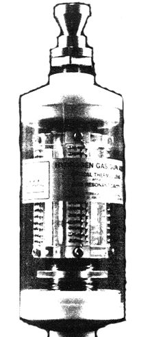
Water Fuel Cell
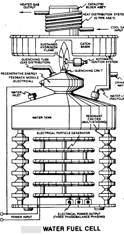
Excerpts from Raum & Zeit 1(6):63-68 (1990) ~
Hydrogen Gas Gun ~
The Electron Extraction Circuit removes, captures, and consumes the
"dislodged" eelctrons (from the gas atoms) to cause the gas atoms to go
into and reach "Critical State", forming highly energized combustiblegas
atoms having missing electrons. Resistive values (R4, R6, R7) and dielectric
constant of gas (Rg) and isolated ground (W) prevents "electron-flow" or
"electron deflection" from occurring within the circuit during pulsing
operations (at resonant frequency) and, therefore, keeps the gas atoms
in critical state by not allowing electron replacement to occur or take
place between the moving gas atoms. The "dislodged" negative charged electrons
are "destroyed" or "consumed" in the form of heat when Amp Consuming Device
(S) such as a light bulb) is positively electrically energized during alternate
pulsing operations. Laser activated or laser primed gas ions repel the
dislodged electrons being consumed. The Electron Extraction Process is
hereinafter called the "Hydrogen Gas Gun" and is placed on top of a Resonant
Cavity Assembly.
Thermal Explosive Energy ~
Exposing the expelling "laser-primed" and electrically chareged combustible
gas ions (exiting from the Gas Resonant Cavity) to a thermal spark or heat
zone causes thermal gas ignition, releasing Thermal Explosive Energy (gtnt)
beyond the Gas-Flame Stage...
Thermal Atomic interaction (gtnt) is caused when the combustible gas
ions (from water) fail to unite or form a Covalent Linkup or Bond between
the water molecule atoms. The oxygen atom having less than four covalent
electrons (Electron Extraction Process) is unable to reach "Stable State"
( 6 to 8 covalent electrons required) when the two hydrogen atoms seek
to form the water molecule during thermal gas ignition. The absorbed laser
energy (Va, Vb, and Vc) weakens the electrical bond between the orbital
electrons and the nucleus of the atom. And, electrical attraction force
being stronger than normal due to the lack of covalent electrons, "locks
onto" and "keeps" the hydrogen electrons... This Atomic Thermal INteraction
between combustible gas opns is from now on called the "Hydrogen Fracturing
Process".
By simply attentuating or varying the voltage amplitude in direct relationship
to voltage pulse rate determines Atmomic Power Yield under control state...
Photon Energy Aids Resonant Action
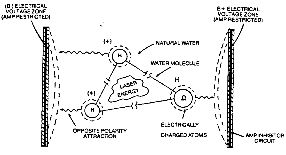
Laser-Injected Resonant Cavity
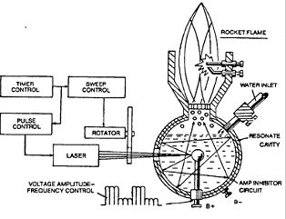
Power Load Distributor
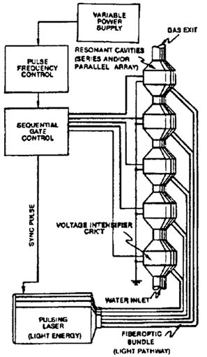
Destabilizing Combustible Gas Ion
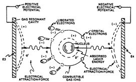
LED Laser Array

Electrical Voltage Zone (Laser-Injected Resonant Cavity)
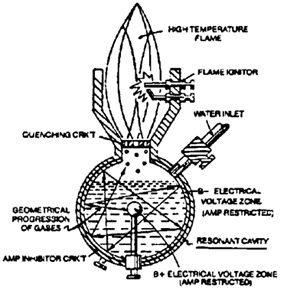
Destabilizing Combustible Gas Ion
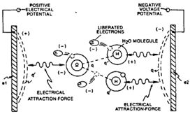
Controlled Energy Yield from Water Atoms
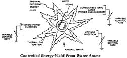
Patents Granted
USP # 4,936,961 - Method for the Production of a Fuel Gas
USP # 4,826,581 - Controlled Production of Thermal Energy from Gases
USP # 4,798,661 - Gas generator voltage control circuit
USP # 4,613,779 ~ Electrical Pulse Generator
USP # 4,613,304 ~ Gas Electrical H Generator
USP # 4,465,455 ~ Start-up/Shut-down for H Gas Burner
USP # 4,421,474 ~ H Gas Burner
USP # 4,389,981 ~ H Gas Injector System for IC Engine
USP # 4,275,950 ~ Light-Guide Lense
USP # 3,970,070 ~ Solar Heating System
USP # 4,265,224 ~ Multi-Stage Solar Storage System
USP # 3,970,070 - Solar heating system
Canada Patent # 1,231,872 ~ H Injector System
CP # 1,233,379 ~ H Gas Injector System for IC Engine
CP # 1,235,669 ~ Controleld H Gas Flame
CP # 1,228,833 ~ Gas Electrical H Generator
CP # 1,227,094 ~ H/Air & Non-Combustible Gas Mixing Combustion
System
CP # 1,234,774 ~ H Generator System
CP # 1,234,773 ~ Resonant Cavity H Generator...
CP # 1,213,671 ~ Electrical Particle Generator
Water Fuel Cell R&D Format
Fuel Cell Technology:
Electrical Polarization Process ~ Producing H gas economically from
water by voltage stimulation
Voltage Intensifier Circuit ~ Controls H gas production on demand
Cluster Array ~ Light manufacturing
Resonant Cavity ~Home/transportation
Laser-Injected Resonant Cavity ~ Medium industry
Atom-Injected Resonant Cavity ~ Heavy industry
H Fracturing Process ~ Controlled energy yield from water atoms (Aircraft/rockets)
Processed H Gas:
Rendering H Gas Safe ~ Adjust H gas burn rate to co-equal natural gasQuenching
Circuit ~ Anti-Spark back
Quenching Tube ~ Distribute H gas without spark ignition
H Ignition ~ Sustain & maintain H flame regardless of gas rate
Startup/Shutdown Electronic Circuit ~ Automatically reignites H gas
after flame-out
H Pipeline Storage ~ Transporting H gas through existing pipelines
safely
H Gas Reclaim ~ Recycling water for H re-use & producing pure drinking
water
Electrical Power Generation:
Electrical Particle Generator (EPG) ~ Using a magnetized gas or slurry
to produce electrical energy without any air-gap
EPG Mechanical Drive System ~ To propel said magnetized gas/slurry
by mechanical displacement
EPG Electromagnetic Drive System ~ To propel said magnetized gas/slurry
by EM deflection
EPG Laser Drive System ~ To propel said magnetized gas/slurry by photon
or particle injection
Magnetic Spin Generator ~ Reorient dyne-axis of said magnetized gas/slurry
by variable pulse voltage
Spiral Transformer Configuration ~ Pass electrical energy at high pulse
voltage frequencies
Electrical Pulsing Generator ~ EM amplifier that produces a variable
voltage frequency
Electrical Feedback Network:
Gas Activated Electrical Generator ~ Using a thermal pump to move said
magnetized gas/slurry to produce electricity
Internal Combustion Electrical Generator ~ Using IC engine power by
processed H gas to move magnetized gas/slurry to produce electricity
Fluid Drive Electrical Generator ~ Using H gas pressure to move magnetized
gas/slurry to produce electricity
Electrical Polarization Generator ~ Using electrically charged gas
to produce electrical energy
Others:
Steam Resonator ~ Producing superheated steam by polar-voltage stimulation
Light-Guide Lens Assembly ~ Collects, redirects, transfers & focuses
solar energy without any moving parts
Infinite Energy 19: 50-51 (1998)
Stanley Meyer, Water-Fuel Cell Inventor & Promoter,
Dies Suddenly
by Eugene Mallove
Stanley A. Meyer, the controversial Ohio inventor who had claimed his
technology could produce a hydrogen-oxygen mixture with a minimal energy
input (compared with conventional electrolysis) died on March 21, 1998.
He had gained a world-wide following of adherents and people who had invested
in his activities --- Water Fuel Cell (Grove City, OH). He was famous for
his claimed "water fueled car" which was exhibited symbolically in the
BBC/CBC 1994 documentary on cold fusion, "Too Close to the Sun".
There were also those who were initially curious about Meyer's work,
such as the editor of this magazine, the late Christopher Tinsley of the
UK, and the late Admiral of the British Navy, Sir Anthony Griffin, but
who became frustrated by being unable --- or, more to the point, not allowed
--- to confirm (or reject finally) Meyer's claims.
I have absolutely NO DOUBT today that Stanley Meyer was his own worst
enemy. IF --- and a very big IF --- he had discovered the technological
process that he had said he had, there is no way that a reasonable, straightforward
marketing strategy would have failed to make his technology quickly spread
worldwide. He could have become very influential and very rich.
There remains a very strong suspicion that he had no such process, even
though he conducted a demonstration (before this writer and another engineer
at the Meyer lab in 1993) of the production of copious hydrogen/oxygen
gas from what visually seemed like a small input power. But Meyer was exceedingly
paranoid and he flatly refused reasonable requests by us and others to
test the performance --- the input/out power ratio, even with the proviso
that we did not have to "look into his black box" of electronics feeding
his rather simply constructed stainless steel electrode, alternating current
and voltage cell. The last such refusal --- this one in public and recorded
on video tape --- was at the ANE meeting in Denver CO in 1997. Then Meyer
loudly and falsely protested to me that he would "lose his patent rights"
if he were to release anything but complete, integrated systems --- such
as a water-fueled vehicle. Excuses, excuses, excuses...
In 1996, Meyer lost a long-lasting Ohio civil court battle accusing
him of "egregious fraud" against a former associate. As was Meyer's custom,
he ascribed this and other alleged assaults on him to various conspiracies.
To television cameras he suggested that he had been offered huge sums of
money to "suppress this technology", but that he had refused those sums.
One had the impression that he really believed that there were conspiracies
against him. That is a tragedy, a very compounded tragedy if he had actually
come up with something novel and useful that he was hiding.
This is a very complex human and scientific story that we shall want
to cover in greater detail in a future issue of Infinite Energy. There
are other processes and inventions that suggest that splitting water molecules
with much greater efficiency than with conventional electrolysis may be
possible. Certainly there are other novelties within water --- "cold fusion"
to be sure --- that really do produce prodigious quantities of energy,
but not in the mode Meyer claimed. For now, here are some of the facts
surrounding Meyer's death:
He was apparently eating dinner at a Grove City OH restaurant, when
it is reported that he jumped up from the table, yelled that he'd been
poisoned", and rushed out into the parking lot, where he collapsed and
died. It has been reported by Meyer's associates that Meyer had just secured
funding for a $50 million research center near Grove City, but there is
no way to confirm or reject this at the moment.
 PFG
Technologie
